
Spectrophotometric pupil confocal-photoacoustic microimaging device and method
A technology of photoacoustic microscopy and imaging devices, which is applied in measuring devices, analyzing materials, and analyzing materials through optical means. It can solve problems such as the inability to realize cell structure images, and achieve easy miniaturization, easy structure, and extended working distance. Effect
Patent Information
- Authority / Receiving Office
- CN · China
- Patent Type
- Applications(China)
- Current Assignee / Owner
- Publication Date
- 2015-06-03
- Estimated Expiration
- Not applicable · inactive patent
Smart Images
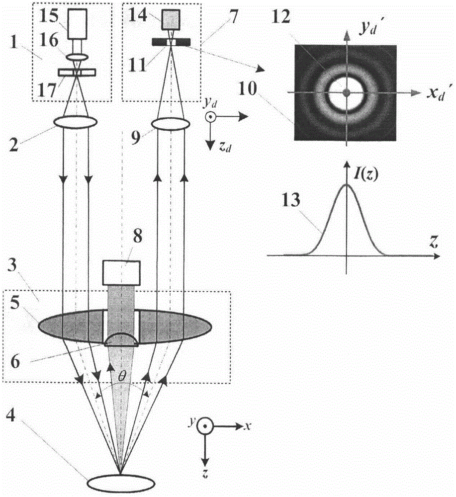
Figure 1 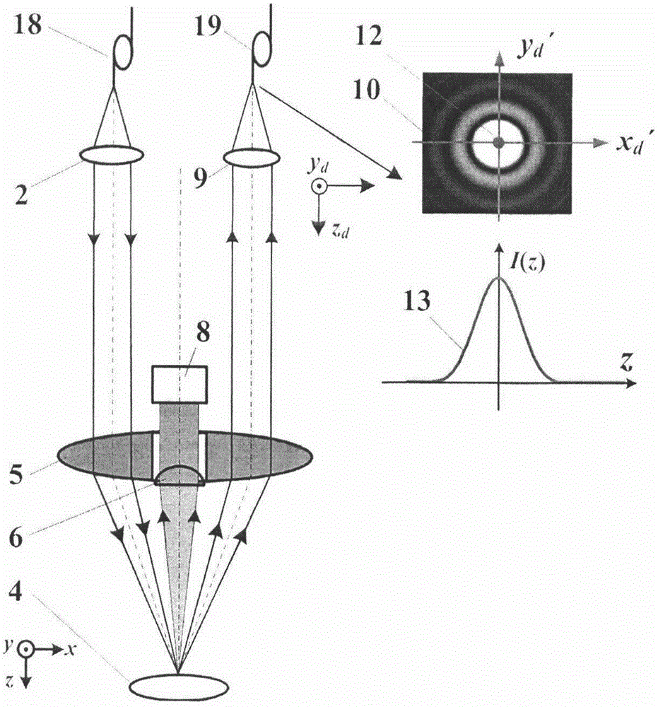
Figure 2 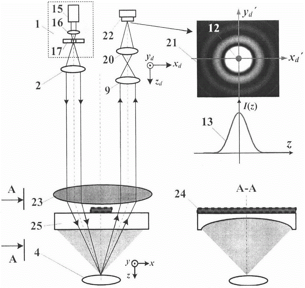
Figure 3
Abstract
Description
technical field
[0001] The invention relates to a pupil-divided confocal-photoacoustic microscopic imaging device and method, and belongs to the technical fields of confocal microscopic imaging technology and photoacoustic microscopic imaging technology. technical background
[0002] Due to its unique tomographic imaging capability and high spatial resolution capability in the optical field, confocal microscopy imaging technology has been widely used as an important technical means in biomedical research, physical chemistry research, material testing, micro-nano testing and other fields. However, the existing confocal microscopic imaging technology mainly uses the scattered light or fluorescence of the object for imaging, which only obtains the structural image of the observed object, and cannot obtain the functional image of cells or biological macromolecules. The depth is only on the order of submillimeters.
[0003] Photoacoustic imaging is based on the photoacoustic sig...
Examples
Embodiment 1
[0040] The embodiment of the present invention is based on Figure 4 The shown split-pupil confocal-photoacoustic microscopy imaging device includes a point light source system 1 composed of a pulsed laser 15, a focusing lens 16 and a pinhole 17, a collimating lens 2, a measuring objective lens 23 and The measured object 4 is sequentially placed in the backscattering direction of the measured object 4 to detect the waveguide 25 with a cylindrical acoustic lens and the ultrasonic transducer array 24 for detecting the photoacoustic signal, and is used to detect the backscattered light of the measured object 4 Or the measurement objective lens 23 of the fluorescent signal, the collecting lens 9 and the detection pinhole 11 located on the focal plane of the collecting lens 9, and the Airy disk micro-region 12 used to segment and detect the Airy disk 10 after the detection pinhole 11 The light intensity detector 14.
[0041] The wavelength, pulse width and repetition frequency of ...
Embodiment 2
[0071] Such as figure 2 As shown, in the split-pupil confocal-photoacoustic microscopy imaging device of Embodiment 1, the point light source composed of the pulse laser 15, the focusing lens 16 and the pinhole 17 at the focal point of the focusing lens 21 is replaced with a fiber-optic point light source 18 System 1; the fiber point detection system 19 replaces the point detection system 7 composed of the detection pinhole 11 located on the focal plane of the collecting lens 9 and the light intensity detector 14 located behind the detection pinhole 11 .
[0072] All the other measuring methods are the same as in Example 1.
Embodiment 3
[0074] Such as image 3 As shown, in the split-pupil confocal-photoacoustic microscopy imaging device of Embodiment 1, the relay magnifying lens 20 and the CCD detector 22 located on the focal plane of the relay magnifying lens 20 are used to enlarge the focal plane spot of the collecting lens 9 A point detection system 7 is formed to replace the point detection system formed by the detection pinhole 11 located on the focal plane of the collecting lens 9 and the light intensity detector 14 located behind the detection pinhole 11 .
[0075] All the other measuring methods are the same as in Example 1.