
Semiconductor device
A semiconductor and conductive type technology, applied in the direction of semiconductor devices, electrical components, circuits, etc., can solve the problems of low round-robin tolerance, large disconnection switch loss, etc., and achieve the effect of reducing the chip area
Patent Information
- Authority / Receiving Office
- CN · China
- Patent Type
- Applications(China)
- Current Assignee / Owner
- Publication Date
- 2017-09-12
- Estimated Expiration
- Not applicable · inactive patent
Smart Images
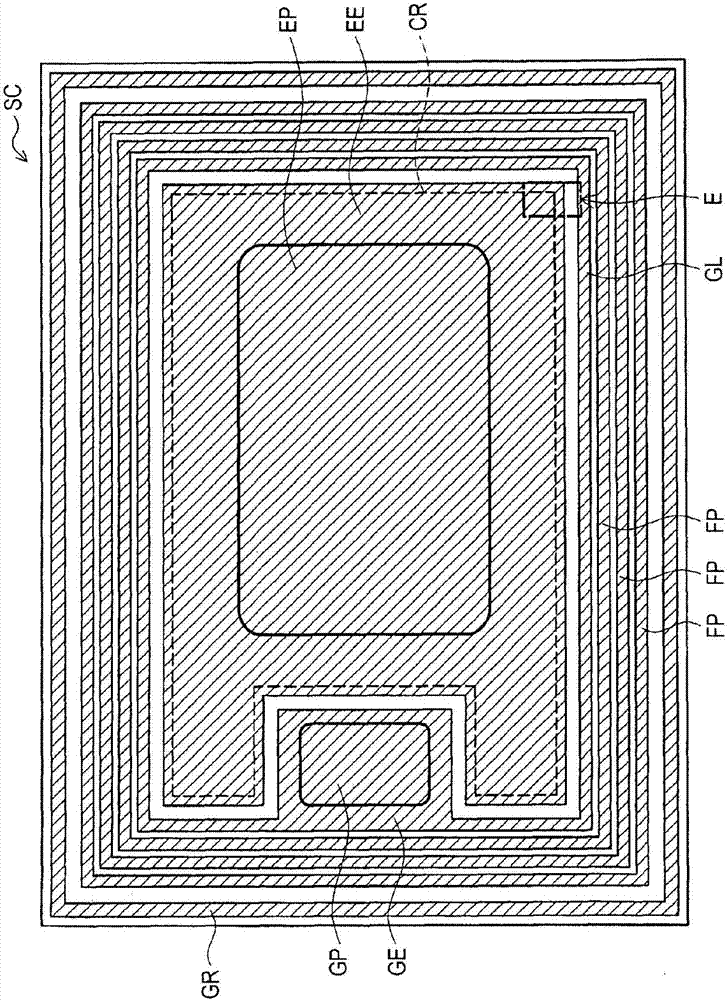
Figure 1 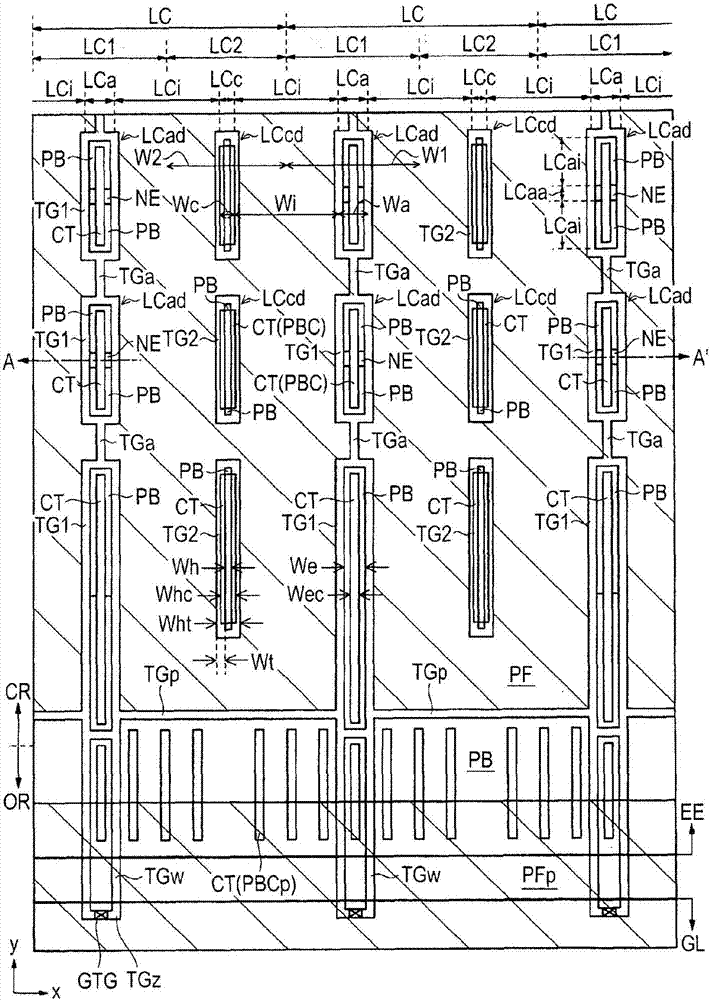
Figure 2 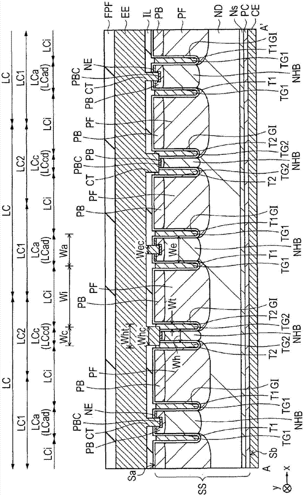
Figure 3
Abstract
Description
[0001] Cross References to Related Applications
[0002] The disclosure of Japanese Patent Application No. 2016-040904 filed on Mar. 3, 2016 including specification, drawings and abstract is incorporated herein by reference in its entirety. technical field
[0003] The present invention relates to semiconductor devices, and preferably can be used in power system semiconductor devices, such as IE (Injection Enhanced) type trench gates comprising both active cells and passive cells in a direction orthogonal to the trench gates IGBT (Insulated Gate Bipolar Transistor). Background technique
[0004] Japanese Unexamined Patent Application Publication No. 2012-256839 discloses an IE type trench gate IGBT. In this IGBT, each linear unit cell region forming a cell region is mainly formed of a linear active cell region and a linear passive cell region. The linear active cell region is divided into an active part and a passive part in its longitudinal direction, and has an emitter r...
Examples
Embodiment 1
[0037]
[0038] will now use figure 1 , figure 2 and image 3 A semiconductor device including the IE type trench gate IGBT according to Embodiment 1 will be described. figure 1 is a main part plan view of the semiconductor chip included in the IE type trench gate IGBT according to Embodiment 1. figure 2 is a principal portion plan view showing an enlarged portion of an active portion of a semiconductor chip according to Embodiment 1. image 3 is a main part sectional view of the IE type trench gate IGBT according to Embodiment 1, and is along figure 2 A cross-sectional view of main parts taken along the line A-A' shown.
[0039] Such as figure 1 As shown, an annular guard ring GR is provided on the upper surface of the outer peripheral portion of the semiconductor chip SC. Inside the ring, there are provided some (single or multiple) annular field plates FP coupled to the annular floating field ring. The guard ring GR and the field plate FP are formed of a metal f...
Embodiment 2
[0121] will now use Figure 10 and Figure 11 A semiconductor device including the IE type trench gate IGBT according to Embodiment 2 is described. Figure 10 is a principal portion plan view showing an enlarged portion of an active portion of a semiconductor chip according to Embodiment 2. Figure 11 is a main part sectional view of the IE type trench gate IGBT according to Embodiment 2, and is along Figure 10 A cross-sectional view of the main part taken along the line B-B' shown.
[0122] Such as Figure 10 and Figure 11 As shown, the difference from the IE type trench gate IGBT according to Embodiment 1 lies in the separate active cell region LCad and the separate hole collector in the IE type trench gate IGBT according to Embodiment 2 Arrangement of the cell area LCcd.
[0123] In the IE type trench gate IGBT according to Embodiment 1 described above, the divided active cell region LCad of the linear active cell region LCa and the divided hole collector cell regio...
Embodiment 3
[0130] will now use Figure 12 , Figure 13 and Figure 14 A semiconductor device including the IE type trench gate IGBT according to Embodiment 3 will be described. Figure 12 is a principal portion plan view showing an enlarged portion of an active portion of a semiconductor chip according to Embodiment 3. Figure 13 is showing Figure 12 A plan view of principal parts of enlarged region C is shown. Figure 14 is a main part sectional view of the IE type trench gate IGBT according to Embodiment 3, and is along Figure 12 The cross-sectional view taken by line D-D' is shown.
[0131] Such as Figure 12 , Figure 13 and Figure 14 As shown, in the IE type trench gate IGBT according to Embodiment 3, the difference from the IE type trench gate IGBT according to Embodiment 1 lies in the formation of separate active cells in the linear active cell region LCa N in area LCad + The width of the type emitter region NE in the second direction (y direction).
[0132] In the d...