

Variable compression ratio system of internal combustion engine, and internal combustion engine
An internal combustion engine and compression ratio technology, which is applied in the field of internal combustion engine auxiliary systems, can solve the problems of complex variable compression ratio structural design, complex EGR structure and controller, and lack of EGR control accuracy, so as to improve fuel economy, improve thermal efficiency, and improve The effect of intake efficiency
Patent Information
- Authority / Receiving Office
- CN · China
- Patent Type
- Applications(China)
- Current Assignee / Owner
- Publication Date
- 2018-06-22
Smart Images
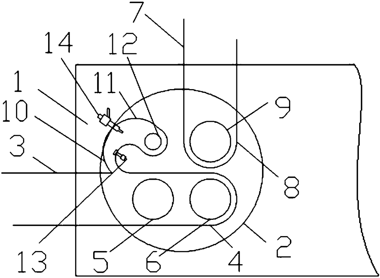
Figure 1 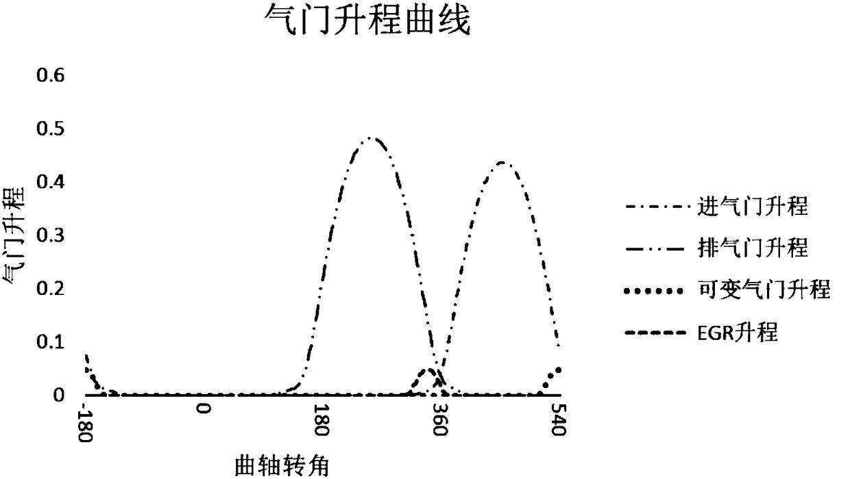
Figure 2
Abstract
Description
Technical field
[0001] The invention relates to the field of internal combustion engine auxiliary systems, in particular to an internal combustion engine variable compression ratio system and an internal combustion engine. Background technique
[0002] Compression ratio refers to the degree of compression of the gas in the cylinder after the piston moves from bottom dead center to top dead center; EGR refers to the internal combustion engine that separates a part of the exhaust gas after combustion and introduces it to the intake side to re-burn. Multiple injection technology can change the trade-off relationship between conventional engine NOx and PM emissions.
[0003] In order to improve fuel economy, prevent deflagration, and reduce engine exhaust pollution, researchers have proposed variable compression ratio, exhaust gas recirculation technology, and multiple injection technology. The variable compression ratio structure design is more complicated, and the internal EGR contro...
Examples
Embodiment Construction
[0027] The present invention will be described in further detail below in conjunction with the accompanying drawings:
[0028] See figure 1 with figure 2 , An internal combustion engine variable compression ratio and EGR adjustment system, including cylinder head 1, cylinder 2, intake manifold 3, intake port 4, intake valve one 5, intake valve two 6, exhaust manifold 7, exhaust Road 8, main exhaust valve 9, auxiliary connecting pipe 10, auxiliary air passage 11, variable auxiliary valve 12 and flow sensor 13;
[0029] Cylinder head 1 is provided on cylinder 2, intake port 4, exhaust port 8 and auxiliary air passage 11 are all provided on cylinder head 1. Intake branch pipe 3 is connected to cylinder 2 through intake port 4 on cylinder head 1. Intake valve one 5 and intake valve two 6 are respectively assembled in intake port 4. Intake valve one 5 and intake valve two 6 are driven by ordinary camshafts, and exhaust branch pipe 7 is connected to cylinder 2 through exhaust port 8. ...