
Laboratory catalytic cracking reactor
A catalytic cracking and reactor technology, applied in the direction of catalytic cracking, cracking, chemical instruments and methods, etc., can solve the problems of large influence of field distribution, inability to accurately reflect the reaction performance of catalysts, complex components, etc.
Patent Information
- Authority / Receiving Office
- CN · China
- Patent Type
- Applications(China)
- Current Assignee / Owner
- Publication Date
- 2021-11-30
Smart Images
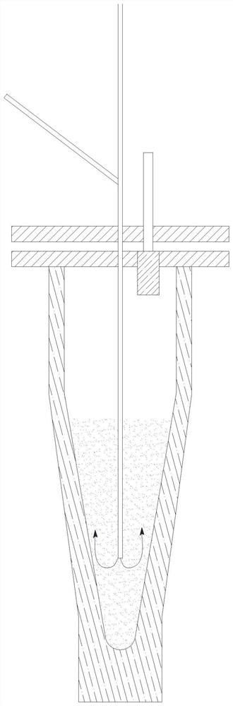
Figure 1 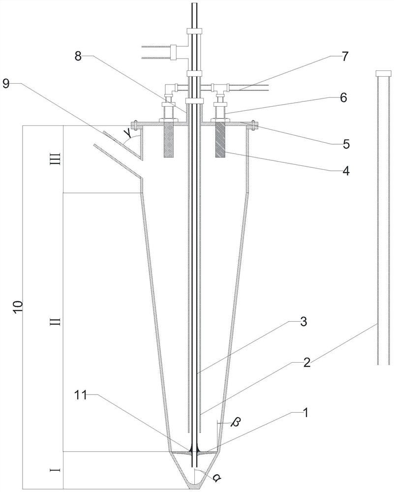
Figure 2 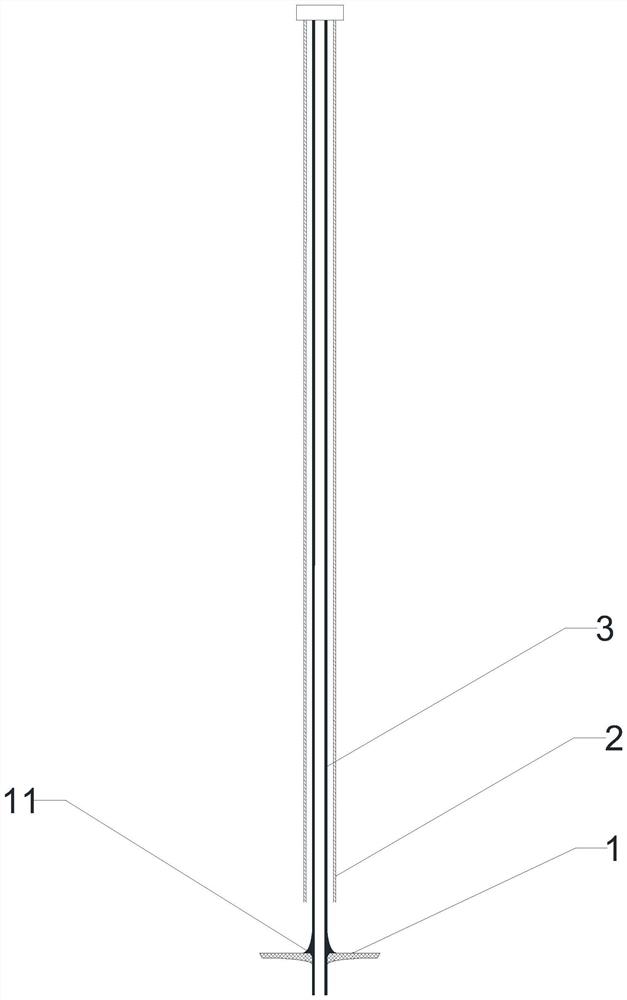
Figure 3
Abstract
Description
technical field
[0001] The invention relates to a laboratory catalytic cracking reaction device. Background technique
[0002] Catalytic cracking is a technology that cracks petroleum hydrocarbons in the presence of catalysts to produce low-carbon olefins. Due to the advantages of wide source of raw materials, easy adjustment of olefin product structure, low energy consumption and less carbon dioxide emissions, catalytic cracking technology has made great progress in recent years. a faster development. In particular, with the diversification of raw materials, making full use of resources, flexibly adjusting products, and improving the economic efficiency of refineries are the main directions of catalytic cracking technology. The process development around this technology, the development of catalysts, or the screening and evaluation of different feedstock oils and catalysts are all inseparable from small laboratory evaluation devices.
[0003] At present, the experimental ...
Examples
Embodiment 1
[0046] This example is used to illustrate the effect of the laboratory catalytic cracking reactor distribution plate and its fluidization pipe provided by the present invention on improving catalyst distribution.
[0047] according to figure 2 The reactor configuration shown in the preparation laboratory catalytic cracking reactor, the distribution plate 1 is at the junction of the reaction section II and the pre-distribution section I, the center of the distribution plate 1 is thick, the edge is thin, the upper surface is flat, the distribution plate 1 The thickness gradually decreases along the track of the elliptical arc with the increase of the radius, and the center of the distribution plate 1 is provided with a cylindrical central hole. The distribution plate 1 adopts alumina ceramics with a porosity of 40%; the reactor adopts the feeding method of top feeding, and the raw material injection pipe 2 enters the reaction section II of the reactor from the top of the reacto...
Embodiment 2
[0050] This example is used to illustrate the effect of adjusting the reaction contact time by changing the height of the feed pipe in the laboratory catalytic cracking reactor provided by the present invention.
[0051] according to figure 2 The shown reactor configuration prepares laboratory catalytic cracking reactor, compares with embodiment 1, and the difference of embodiment 2 is that the length of raw material injection pipe 2 is 80% of the length of embodiment 1 raw material injection pipe, to reduce reaction time . The catalytic cracking reaction was carried out under the same conditions as in Comparative Example 1, and the analysis results are shown in Table 3.
Embodiment 3
[0053] This example is used to illustrate the effect of adjusting the reaction contact time by changing the height of the feed pipe in the laboratory catalytic cracking reactor provided by the present invention.
[0054] according to figure 2 The shown reactor configuration prepares laboratory catalytic cracking reactor, compared with embodiment 1, the difference of embodiment 3 is that the length of raw material injection pipe 2 is 130% of the length of embodiment 1 raw material injection pipe, to increase the reaction time . The catalytic cracking reaction was carried out under the same conditions as in Comparative Example 1, and the analysis results are shown in Table 3.
[0055] Table 1
[0056] project data Density(20℃)(kg·m -3 )
900.8 Distillation range (℃) initial boiling point 213 10% 343 30% 387 50% 483 Carbon residue mass fraction (%) 4.74 Total sulfur mass fraction (%) 0.16
[0057] Table 2
[00...