
Capacitive sensor having bending portion and flat portion
a capacitive sensor and bending portion technology, applied in the field of capacitive sensors, can solve the problems of affecting the function of the capacitive sensor sensor, the resistance of the bridge wiring member may change accordingly, and so as to reduce the possibility of the sensor function becoming defective and the damage in the bridge structure.
Patent Information
- Authority / Receiving Office
- US · United States
- Patent Type
- Patents(United States)
- Current Assignee / Owner
- Publication Date
- 2020-02-18
Smart Images
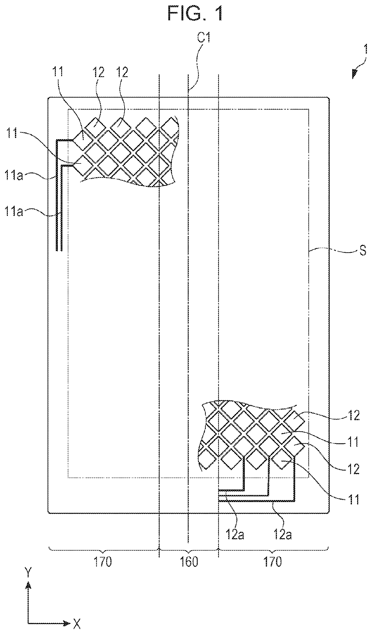
Figure 1 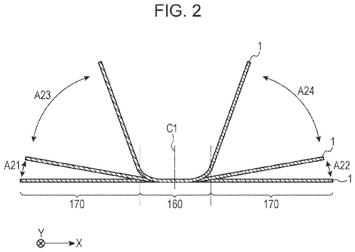
Figure 2 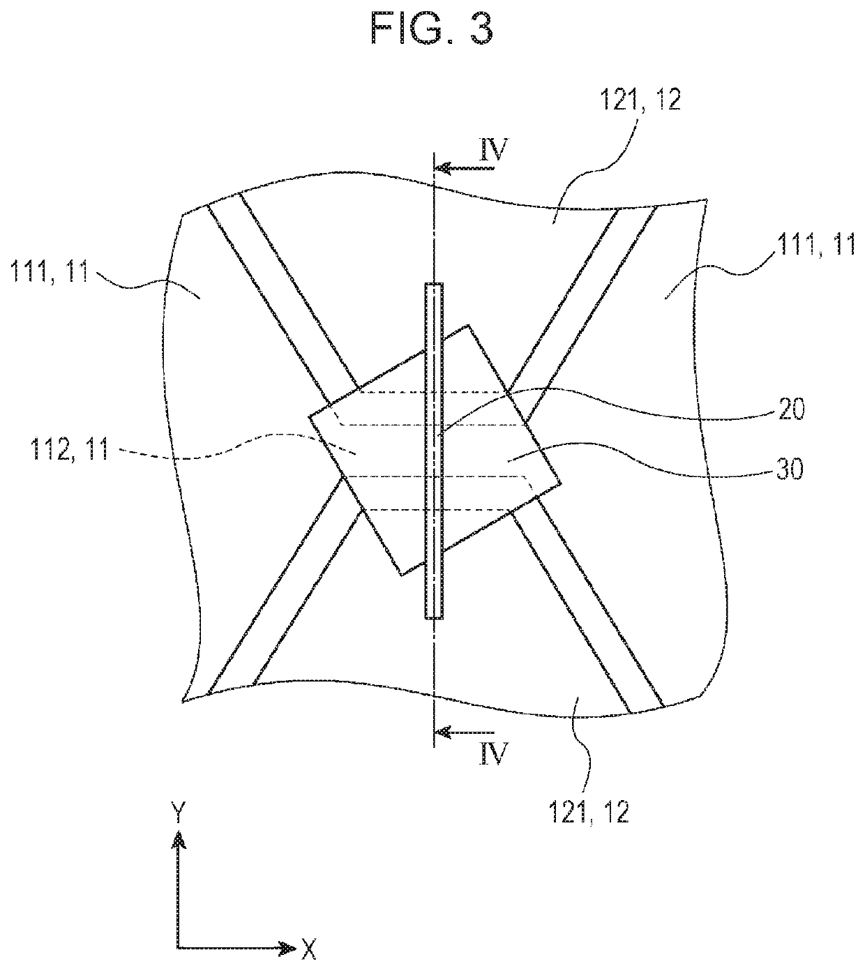
Figure 3
Abstract
Description
CLAIM OF PRIORITY
[0001] This application is a Continuation of International Application No. PCT / JP2016 / 086535 filed on Dec. 8, 2016, which claims benefit of Japanese Patent Application No. 2015-242043 filed on Dec. 11, 2015. The entire contents of each application noted above are hereby incorporated by reference.BACKGROUND OF THE INVENTION1. Field of the Invention
[0002] The present invention relates to a capacitive sensor and relates specifically to a capacitive sensor that has a bridge structure (electrode-crossing structure) and that is bendable.2. Description of the Related Art
[0003] A typical capacitive sensor includes a plurality of transparent electrodes having light transparency. In such a capacitive sensor, which has a bridge structure, a plurality of first transparent electrodes are coupled to each other in a first direction via bridge wires, and a plurality of second transparent electrodes are coupled to each other in a second direction via coupling members. The plurality of ...
Examples
Embodiment Construction
[0034]Hereinafter, an embodiment of the present invention will be described with reference to the drawings. Note that, in the drawings, similar constituent elements are assigned the same reference numerals, and detailed descriptions thereof will be omitted as appropriate.
[0035]FIG. 1 is a schematic plan view illustrating a capacitive sensor according to the present embodiment. FIG. 2 is a schematic plan view illustrating a state where the capacitive sensor according to the present embodiment is bent. FIG. 3 is a schematic enlarged view illustrating a bridge wiring member in a bending portion. FIG. 4 is a schematic cross-sectional view taken along line IV-IV illustrated in FIG. 3. FIG. 5 is a schematic enlarged view illustrating a bridge wiring member in a flat portion. FIG. 6 is a schematic cross-sectional view taken along line VI-VI illustrated in FIG. 5.
[0036]The terms “transparent” and “light transparency” used herein indicate a state where the visible-light transmittance is 50% ...