
Fiber adhesive material
a technology of adhesive materials and fibers, applied in the direction of laminated elements, semiconductor/solid-state device details, broidering machines, etc., can solve the problems of limiting the overall performance of the thermal control system, requiring special fixation for attaching, and not being reusable or easily removabl
Patent Information
- Authority / Receiving Office
- US · United States
- Patent Type
- Applications(United States)
- Current Assignee / Owner
- Publication Date
- 2004-04-15
- Estimated Expiration
- Not applicable · inactive patent
Smart Images
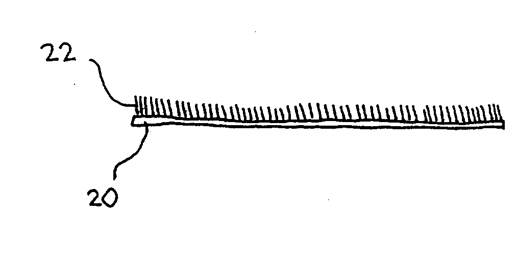
Figure 1 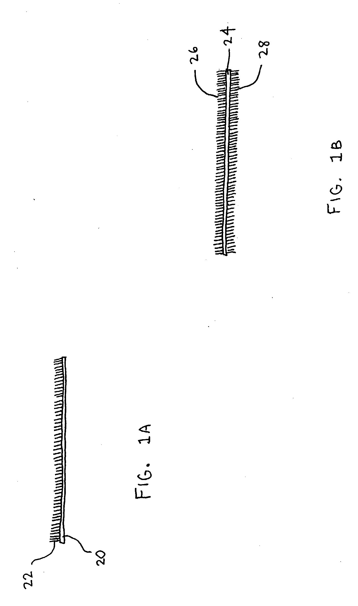
Figure 2 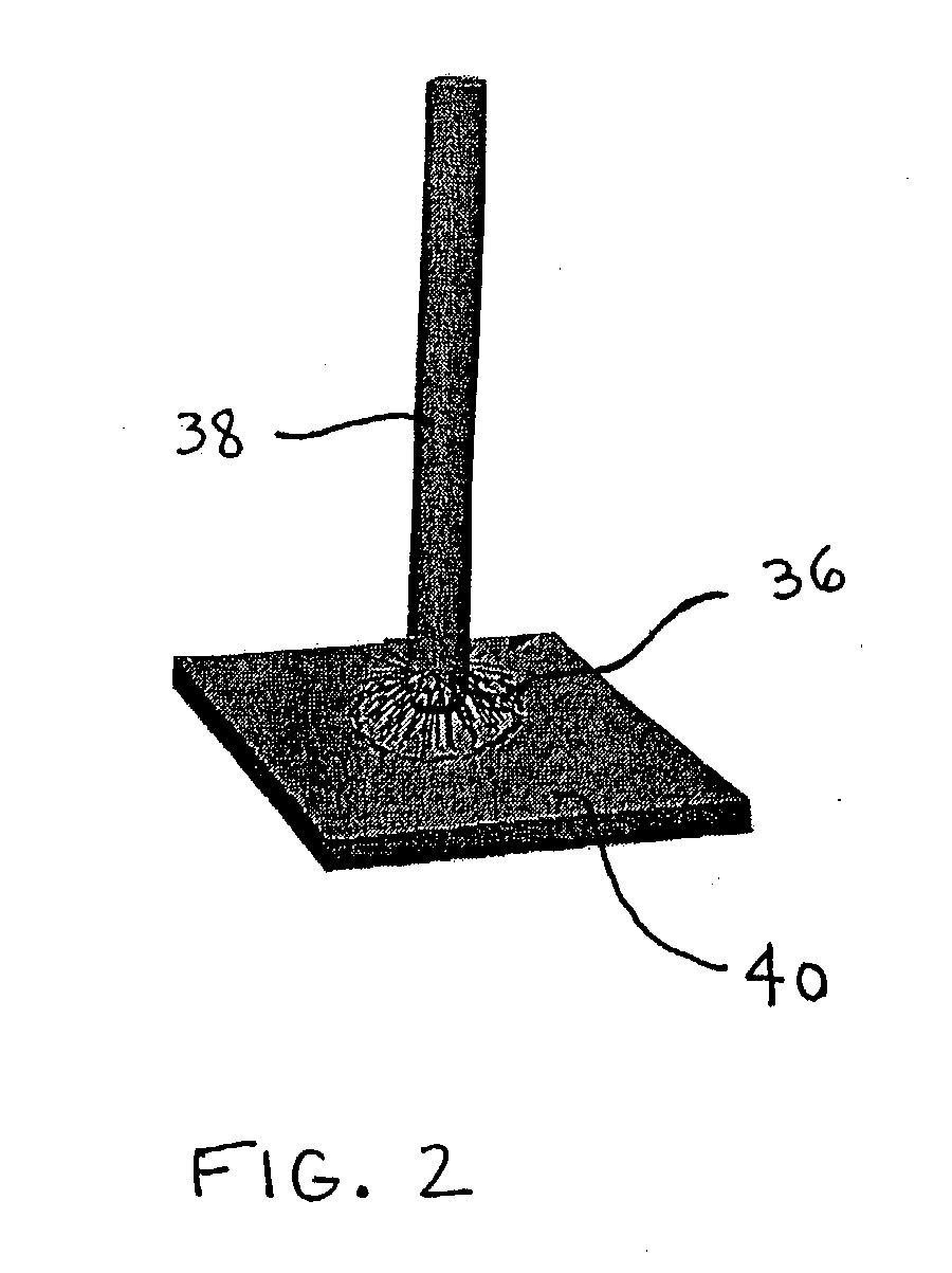
Figure 3
Abstract
Description
[0001] This application claims priority to U.S. Provisional Patent Application Serial No. 60 / 390,239, titled Dendritic Adhesive, and filed on Jun. 17, 2002 and is a continuation-in-part of U.S. patent application Ser. No. 09 / 593,587, titled Thermal Interface, and filed on Jun. 13, 2000, which claims priority to U.S. Provisional Patent Application Serial No. 60 / 139,443, entitled Thermal Interface, and filed on Jun. 14, 1999. The entire disclosures of all of these applications are hereby incorporated by reference in their entirety.
[0002] 1. Field of the Invention
[0003] The invention relates to adhesive materials such as tapes that provide a dry and reusable medium for adhering two surfaces together.
[0004] 2. Description of Related Art
[0005] Much of thermal management involves the transfer of heat from one element to another. While individual elements might have very high conductance, the heat transfer rate between contact surfaces of the two elements can limit overall performance of t...
Examples
Embodiment Construction
[0064] Pitch carbon fiber gasket sample cs7-144 was processed in the PE-HF CVD reactor under the conditions listed in Table 1
1TABLE 1 PE-HF CVD deposition conditions of pitch fiber gasket sample Sample# cs7-144 Mounting Lying flat on anode conditions Plasma power 160 W HF power 300 W Max temperature 527.degree. C. Plasma etch time 12 min Deposition time 5 min Hydrocarbon gas Acetylene Mass gain 4.6 mg (5 %) Resulting deposit Heavy, bottom side
[0065] After the chamber cooled, the sample was removed and examined under the microscope. The bottom of Sample cs7-144 was covered with carbon deposit that was visible under the optical microscope. The 90.5 mg sample had gained 4.6 mg, which corresponds to a 4 micron-thick, uniform layer of carbon over one surface. Some areas displayed thicker deposits than others did. The variation may reflect variation in local temperature, hydrocarbon concentration, and / or catalyst microstructure.
[0066] FIG. 5 is a 250.times. SEM image of a pitch carbon fib...