
Method and apparatus for extinguishing a fire in an enclosed space
Patent Information
- Authority / Receiving Office
- US · United States
- Current Assignee / Owner
- Publication Date
- 2005-06-30
Smart Images
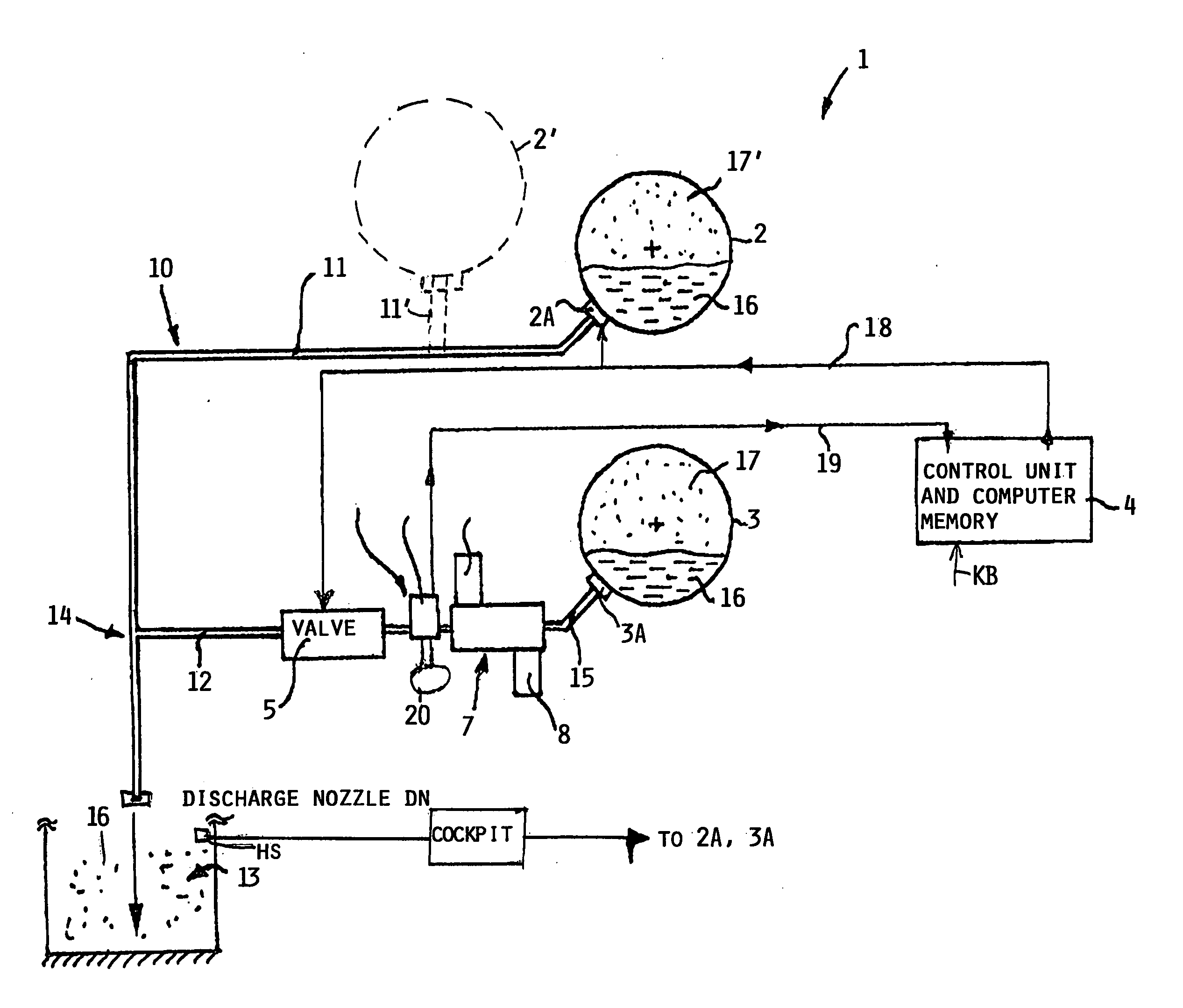
Figure 1 
Figure 2 
Figure 3
Abstract
Description
PRIORITY CLAIM
[0001] This application is based on and claims the priority under 35 U.S.C. §119 of German Patent Application 103 61 020.0, filed on Dec. 24, 2003, the entire disclosure of which is incorporated herein by reference. FIELD OF THE INVENTION
[0002] A fire is extinguished in any enclosed space, for example in the cargo hold of an aircraft, a ship, or any other conveyance having an enclosed space, such as a car. A fire extinguishing agent is stored in at least one container which is connected through a pipe system to at least one discharge nozzle in the enclosed space. A method for extinguishing a fire uses such system. BACKGROUND INFORMATION
[0003] Firefighting in civilian, particularly commercial, and military aircraft requires equipment which uses halons, also known as halogen hydrocarbons, as fire extinguishing agents. However, the use of such halons is discouraged in view of their presumed adverse effect on the environment. Thus, halon replacement agents are known whi...
Examples
Embodiment Construction
[0025] The present fire extinguishing or firefighting system 1 comprises at least one container 3 for holding a fire extinguishing agent 16. Preferably, a plurality of such containers are used, for example the containers 2, 3 and 2′. The number of containers is only limited with due regard to the estimated quantity or volume of a fire extinguishing agent 16 needed for any particular volume of an enclosed space.
[0026] As shown in FIG. 1, the system 1 comprises a first container 3 holding extinguishing agent 16 below a nitrogen cushion 17. The container 3 is connected through a frangible closure such as a membrane 3A to a pipe section 15 which leads to a filter unit 7 including a water adsorption filter 8 and a solid particle filter 9. The filter unit 7 in turn is connected through a pipe section to a sensor unit 6 including a pressure sensor 20 and a temperature sensor 21. The sensor section 6 is connected through a further pipe section to a closed loop controllable valve, such as a...