
Exhaust gas treatment method and system for cement burning facility
a technology of exhaust gas treatment and cement burning facility, which is applied in the direction of auxillary pretreatment, separation process, filtration separation, etc., can solve the problems of blockage and blockage of the facility, and achieve the effect of preventing an increase in chlorine bypass amount, reducing the rate of chlorine particles, and reducing the amount of chlorine bypass
Patent Information
- Authority / Receiving Office
- US · United States
- Patent Type
- Applications(United States)
- Current Assignee / Owner
- Publication Date
- 2010-04-08
Smart Images
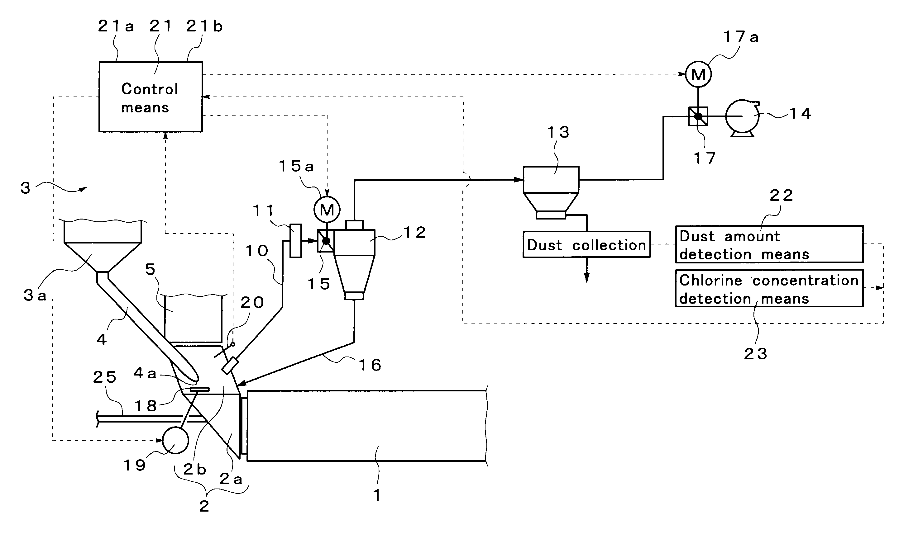
Figure 1 
Figure 2 
Figure 3
Abstract
Description
BACKGROUND OF THE INVENTION
[0001] 1. Field of the Invention
[0002] The present invention relates to an exhaust gas treatment method and system for a cement burning facility using a chlorine bypass to inhibit a possible increase in the concentration of chlorine in the system of the cement burning facility.
[0003] 2. Description of the Related Art
[0004] In recent years, in order to solve waste disposal problems, various wastes are used as part of a cement material or part of a heating fuel used in a cement kiln. However, when wastes such as a synthetic resin are fed into the cement kiln as part of the fuel, a volatile chlorine component is generated during combustion. The chlorine component is entrained in exhaust gas discharged from the cement kiln and fed to an upper stage side of a preheater. However, when the atmosphere temperature decreases to at most the melting point of the chlorine component as the exhaust gas is transferred to the upper stage side of the preheater, the chlorine com...
Examples
Embodiment Construction
[0069]FIG. 1 shows an embodiment of an exhaust gas treatment system for a cement burning facility according to the present invention.
[0070]First, a cement manufacturing facility in which the exhaust gas treatment system is installed will be described. Reference numeral 1 in FIG. 1 denotes a cement kiln configured to burn a cement material. The cement kiln 1 is a rotary kiln configured so as to be axially rotatable. In the left end part of the figure, a kiln inlet part 2 is provided which includes a kiln inlet part housing 2a supporting the rotary portion, and a rising part 2b of the kiln inlet part housing.
[0071]Furthermore, a preheater 3 configured to preheat a cement material is provided on the upper stage side of the kiln inlet part 2. A main burner configured to heat the inside of the kiln is provided in a kiln outlet part (not shown in the drawings) located in the right of the figure.
[0072]Here, the preheater 3 is composed of a plurality of stages (for example, four stages) of ...