
Current trigger circuit and switching power converter using the same
a current trigger circuit and current trigger technology, applied in the direction of ignition automatic control, process and machine control, instruments, etc., can solve the problems of circuit with high conversion efficiency and easy failure of detection, and achieve the effect of reducing power consumption, increasing conversion efficiency, and easy affecting
Patent Information
- Authority / Receiving Office
- US · United States
- Patent Type
- Applications(United States)
- Current Assignee / Owner
- Publication Date
- 2010-09-30
Smart Images
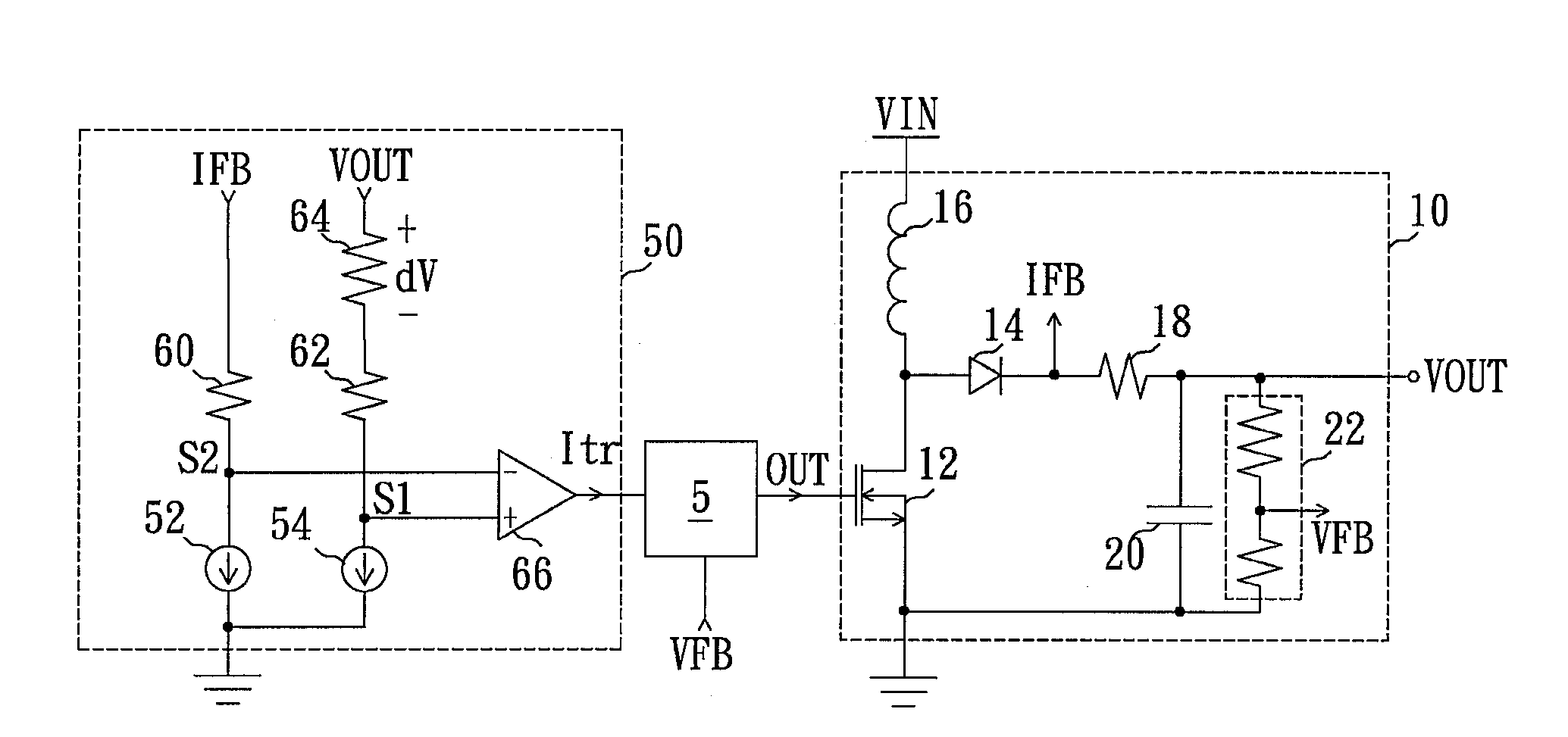
Figure 1 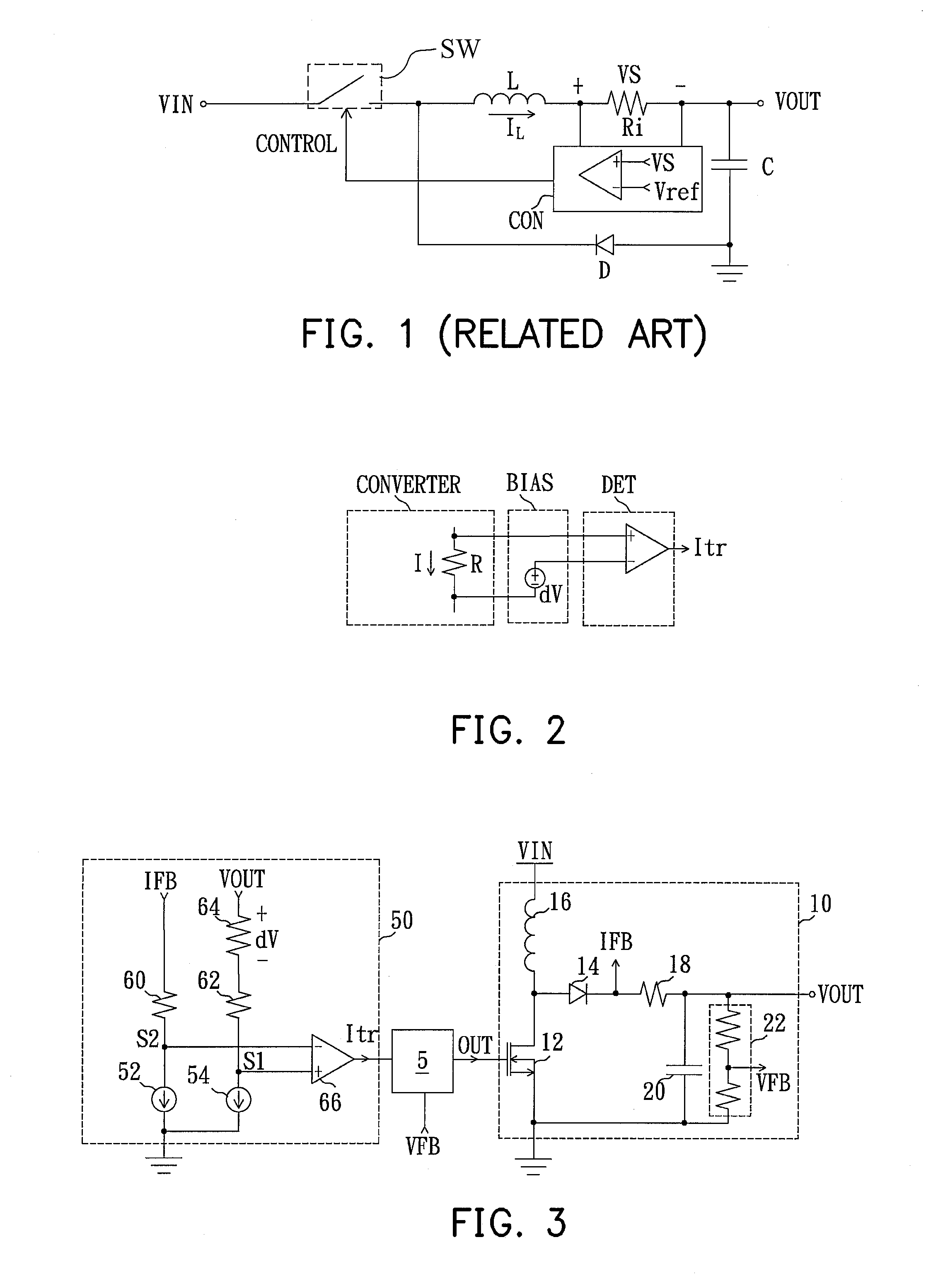
Figure 2 
Figure 3
Abstract
Description
CROSS-REFERENCE TO RELATED APPLICATION
[0001] This application claims the priority benefit of Taiwan application serial no. 098109814, filed on Mar. 26, 2009. The entirety of the above-mentioned patent application is hereby incorporated by reference herein and made a part of specification.BACKGROUND OF THE INVENTION
[0002] 1. Field of the Invention
[0003] The present invention generally relates to a switching power converter and a current trigger circuit, and more particularly, to a switching power converter and a current trigger circuit capable of comparing a bias voltage with a voltage difference in a detecting element to detect a current flowing through the detecting element.
[0004] 2. Description of Related Art
[0005] Please refer to FIG. 1, which is a schematic diagram of a buck DC / DC converting circuit for converting an input voltage VIN to an output voltage VOUT in a related art. The buck DC / DC converting circuit includes a switch SW, an inductor L, a capacitor C, a diode D, a detectin...
Examples
Embodiment Construction
[0019]Please refer to FIG. 2, which is a schematic diagram of a current trigger circuit according to an exemplary embodiment consistent with the present invention. The converting circuit CONVERTER has a detecting resistor R, which a current I passes through. A bias voltage unit BIAS has a first detecting end and a second detecting end respectively coupled to two terminals of the detecting resistor R. In addition, the bias voltage unit BIAS provides a bias voltage dV to one of the first detecting end and the second detecting end. A trigger unit DET is coupled to the bias voltage unit BIAS. While a voltage difference I*R across the detecting resistor R is raised up to a level higher than the bias voltage dV, the trigger unit DET immediately generates a current trigger signal Itr with a high level. Since noise interferences from circuits of the first detecting end and the second detecting end coupled to the trigger unit DET are mutually offset, current detection is almost not affected ...