
Enhanced Sensitivity Line Field Detection
Patent Information
- Authority / Receiving Office
- US · United States
- Current Assignee / Owner
- Publication Date
- 2013-09-05
- Estimated Expiration
- Not applicable · inactive patent
Smart Images
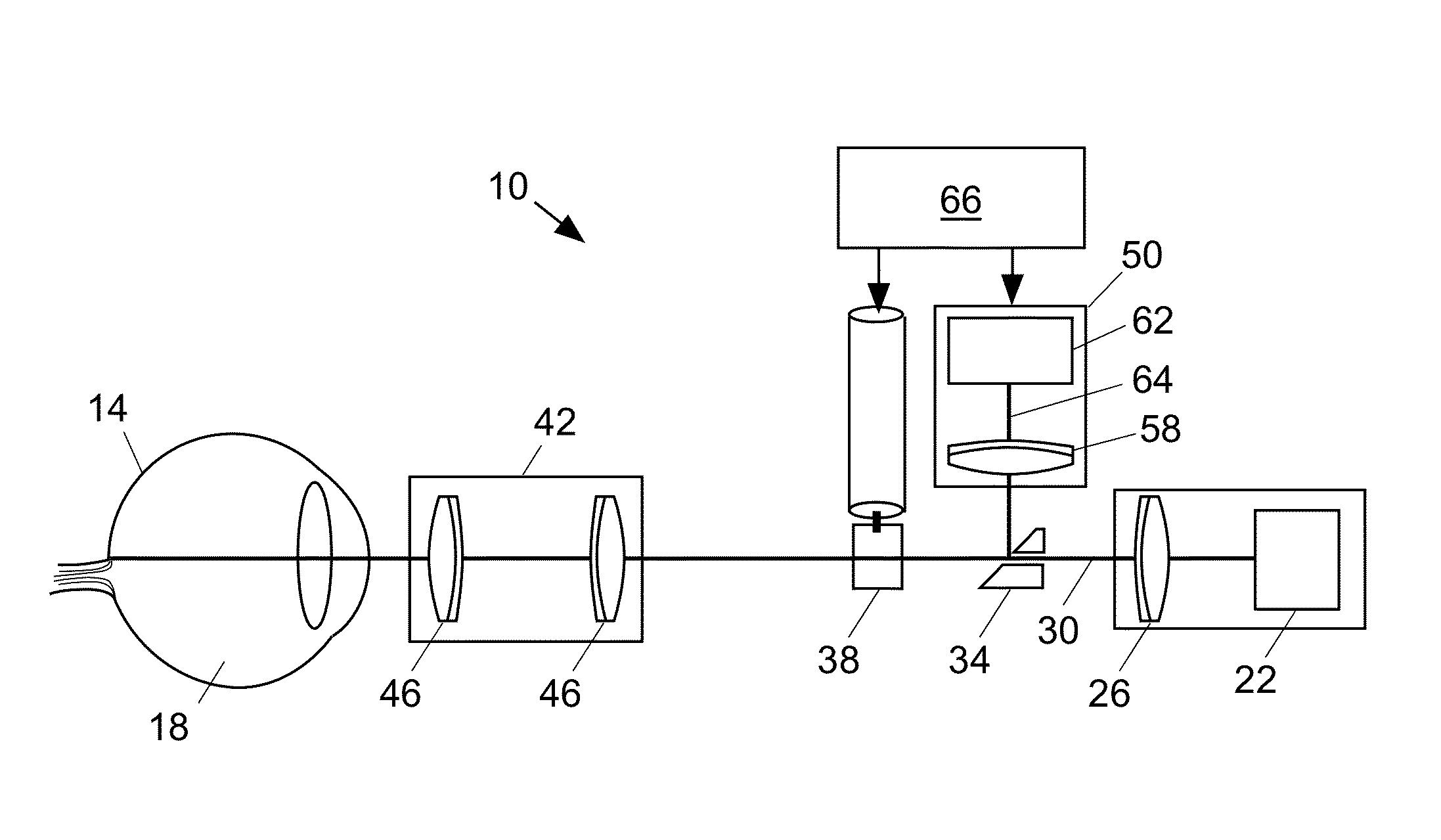
Figure 1 
Figure 2 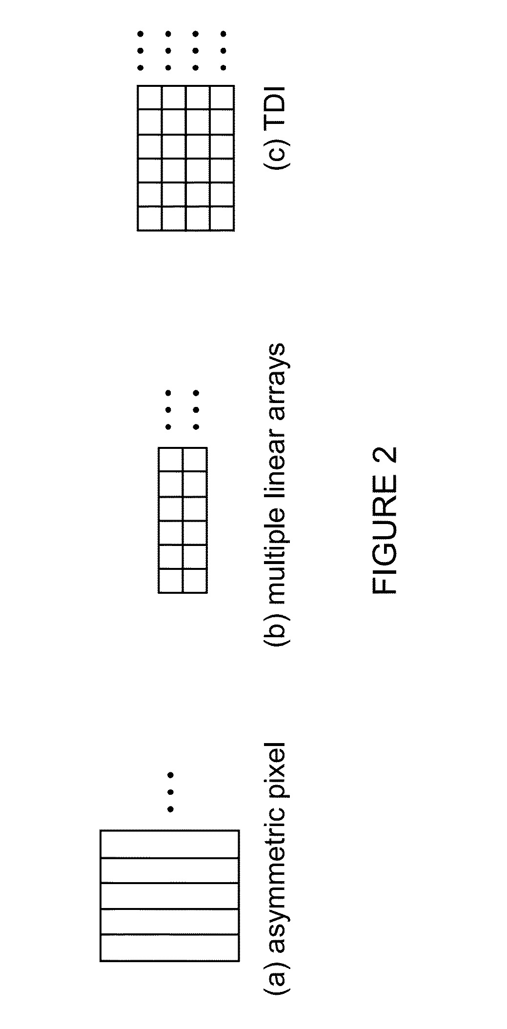
Figure 3
Abstract
Description
GOVERNMENT RIGHTS
[0001] The invention was made with government support under Department of Defense contract no. W81XWH-06-C-0397. The government has certain rights in the invention.FIELD OF THE INVENTION
[0002] The invention relates generally to enhanced line field retinal imaging, and more particularly, to a line scanning ophthalmoscope incorporating a detection device with asymmetric pixels, a detection device with multiple adjacent linear arrays, and / or a detection device using a time delay and integration (TDI) architecture.BACKGROUND
[0003] In vivo ophthalmic images are produced by back-reflected light from ocular tissue (e.g., retina, cornea, lens, etc.) and can overcome the problem of weak signals for applications such as detection of exogenous and endogenous fluorescence, molecular signatures, high-speed dynamics, multiphoton imaging, and others. In general, fundus imaging can be divided into three major device categories: flood illumination, line scanning or line field, and conf...
Examples
Embodiment Construction
[0040]FIG. 1 shows an illustrative embodiment of a retinal imaging device 10 including and an optical system configured to (i) scan a portion of a retina 14 of an eye 18 with a line of light, (ii) descan reflected light from the scanned portion of the retina, and (iii) provide output light in a line focus configuration. The optical system can be a line scan ophthalmoscope (LSO), e.g., a line scan laser ophthalmoscope (LSLO) or a LSO using a diode or superluminescent diode (SLD). The optical system can provide an image having a wide field of view.
[0041]The optical system includes a source 22 and a lens system 26 to form the input beam 30 into a line of light. The optical system includes a beam separator 34 including an aperture through which the line of light passes and includes a galvanometer 38 to control the position of the imaging beam. The optical system includes an ocular interface 42 including one or more ophthalmic lens 46 for focusing the line of light in the retina.
[0042]Li...