
Simplified control method for a three-phase ac voltage-dc voltage converter
a voltage converter and three-phase ac technology, applied in the direction of power conversion systems, climate sustainability, efficient power electronics conversion, etc., can solve the problems of complex methods, many sensors, and many methods for feedback controlling voltages to currents in the methods of prior art, and achieve very accurate voltage and current sensors, heavy control software, and simple control methods.
Patent Information
- Authority / Receiving Office
- US · United States
- Current Assignee / Owner
- Publication Date
- 2014-01-09
Smart Images
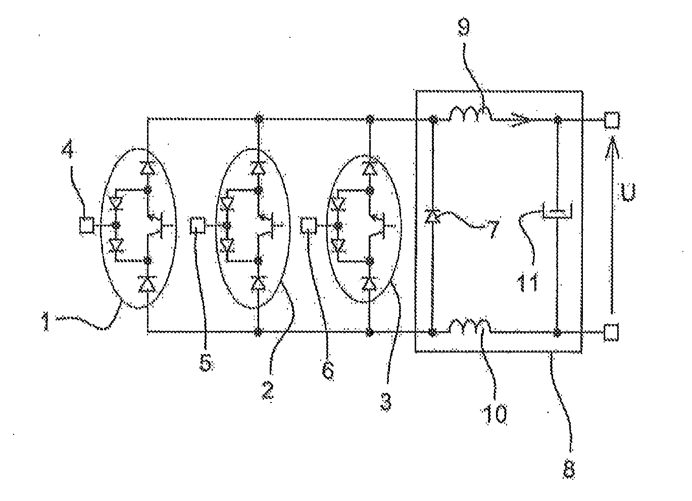
Figure 1 
Figure 2 
Figure 3
Abstract
Description
TECHNICAL FIELD
[0001] The present invention relates to a method for controlling converter from a three-phase AC voltage to a DC voltage.STATE OF PRIOR ART
[0002] FIG. 1 represents a “three-phase buck” type converter which enables a three-phase AC voltage to be converted into DC voltage. This converter includes three switches 1, 2, 3 to which each of the phases 4, 5, 6 of the three-phase AC voltage is connected. The three switches 1, 2, 3 are connected in parallel to each other. The three-phase buck converter also includes a free wheel diode 7 connected in antiparallel on the DC bus as well as an output filter 8 including two inductors 9, 10 and a capacitor 11.
[0003] The free wheel diode allows a current continuity when the switches of the circuit are open. This is essential when the current flows in inductors as is the case here because the current should not be suddenly interrupted in an inductor.
[0004] Generally, to control such a converter, prior art proposes to measure the input volt...
Examples
Embodiment Construction
[0063]FIG. 1 represents a converter for converting a three-phase AC input voltage into a DC output voltage. FIG. 11 represents the symbol of a converter. The converter of FIG. 1 is called a “three-phase buck converter”. The control method is applicable for example to this converter. FIG. 13 represents a block diagram of a buck converter to which the invention is applicable.
[0064]However, the invention is not restricted to this type of converter. The control method according to the invention could for example be applicable to “boost” type converters. FIG. 12 represents a block diagram of a boost converter. Further, the invention is not restricted to the three-phase voltage converters, and could be used for converters from n-phase voltages into a DC voltage.
[0065]The converter of FIG. 1 includes three switches 1, 2, 3 to which is connected each of the phases 4, 5, 6 of the three-phase AC input voltage. The three switches 1, 2, 3 are connected in parallel to each other. The converter a...