
Light source device, projector, and method for controlling light source device
Patent Information
- Authority / Receiving Office
- US · United States
- Current Assignee / Owner
- Publication Date
- 2018-08-02
Smart Images
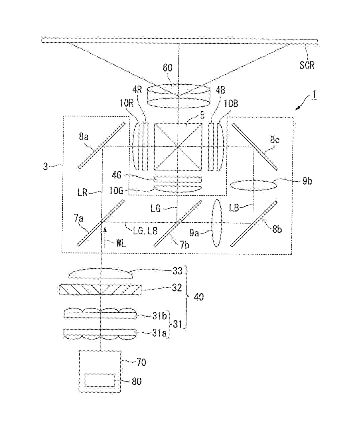
Figure 1 
Figure 2 
Figure 3
Abstract
Description
BACKGROUND1. Technical Field
[0001] The present invention relates to a light source device, a projector, and a method for controlling a light source device.2. Related Art
[0002] A fluorescent light emitting device which has a fluorescent wheel and a wheel motor for rotationally driving the fluorescent wheel is known. For example, JP-A-2012-053279 discloses a fluorescent light emitting device installed in a projector.
[0003] In the fluorescent light emitting device (light source device) as described above, in order to diffuse and radiate heat generated by excitation light cast on the fluorescent wheel (first optical element), the fluorescent wheel is rotated by the wheel motor (first drive unit) and the position where the excitation light is cast on the fluorescent wheel is thus changed. Therefore, for example, if the excitation light is cast on the fluorescent wheel without rotating the fluorescent wheel, the fluorescent wheel may be damaged by the heat of the excitation light in some cas...
Examples
first embodiment
[0044]FIG. 1 is schematic configuration view showing a projector 1 according to this embodiment. As shown in FIG. 1, the projector 1 according to this embodiment is a projection-type image display device which displays a color image on a screen SCR. The projector 1 has a light source device 70, a uniform illumination system 40, a color separation system 3, a light modulation device 4R for red light, a light modulation device 4G for green light, a light modulation device 4B for blue light, a light combining system 5, and a projection system 60.
[0045]The light source device 70 emits white illumination light WL toward the uniform illumination system 40.
[0046]The uniform illumination system 40 has a homogenizer system 31, a polarization conversion element 32, and a superimposing system 33. The homogenizer system 31 is configured of a first multi-lens array 31a and a second multi-lens array 31b. The uniform illumination system 40 uniformizes the intensity distribution of the illumination...
second embodiment
[0123]A second embodiment is different from the first embodiment in that the control unit 80 sets the number of rotations of each element to be smaller than each number of rotations for lighting in the first period PH1. The description of components similar to those in the foregoing embodiment is omitted in some cases, where these components are denoted by the same reference signs or the like.
[0124]FIG. 6 is a flowchart showing an example of a control procedure of the control unit 80 in this embodiment. FIG. 7 is a timing chart showing an example of the relationship between the power PP of the projector 1, the quantity of light LP of the light source unit 2, the power MP1 of the first motor 50 and the power MP2 of the second motor 53, the number of rotations RC of the wavelength conversion element 46, and the number of rotations RD of the diffusion element 52. FIG. 7 shows the case where, after the power PP of the projector 1 is turned off, the power PP of the projector 1 is turned ...
third embodiment
[0137]A third embodiment is different from the second embodiment in that the control unit 80 turns on the light source unit 2 when the power PP of the projector 1 is turned on again in the first period PH1. The description of components similar to those in the foregoing embodiments is omitted in some cases, where these components are denoted by the same reference signs or the like.
[0138]FIG. 8 is a timing chart showing an example of the relationship between the power PP of the projector 1, the quantity of light LP of the light source unit 2, the power MP1 of the first motor 50 and the power MP2 of the second motor 53, the number of rotations RC of the wavelength conversion element 46, and the number of rotations RD of the diffusion element 52.
[0139]In this embodiment, when turning on the light source unit 2 in the first period PH1, the control unit 80 increases the number of rotations of each element from each predetermined number of rotations, then turns on the light source unit 2 ...