
Surface profile detection apparatus of burden in blast furnace and operation method
Patent Information
- Authority / Receiving Office
- US · United States
- Current Assignee / Owner
- Publication Date
- 2021-08-19
Smart Images
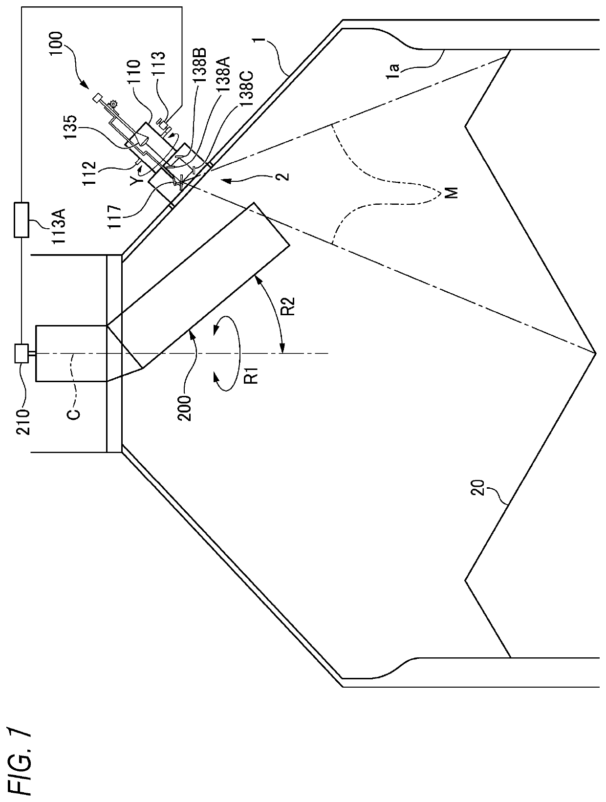
Figure 1 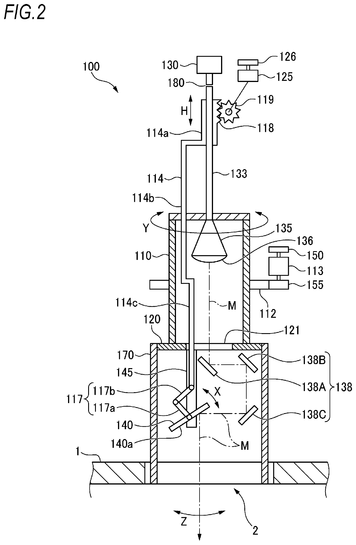
Figure 2 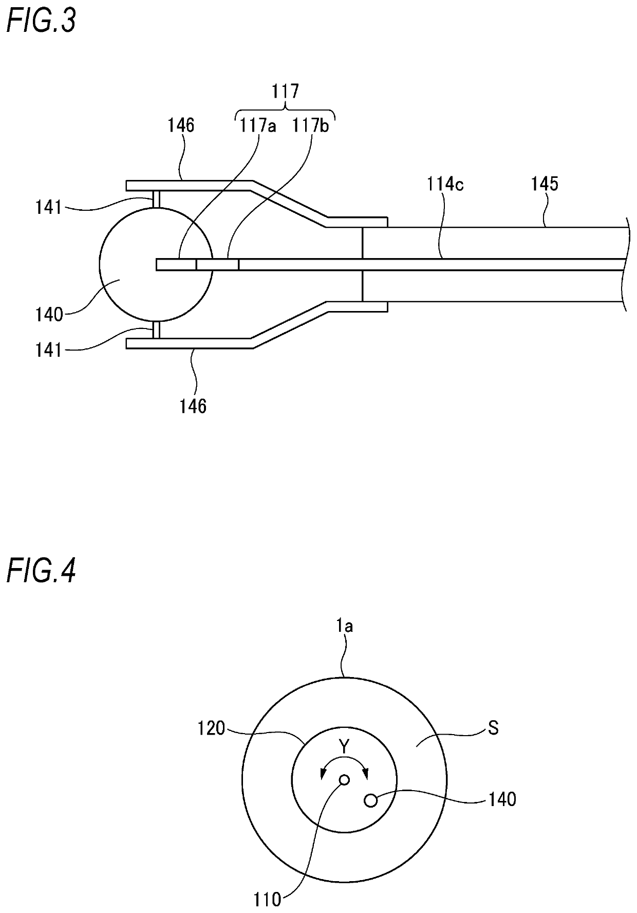
Figure 3
Abstract
Description
TECHNICAL FIELD
[0001] The present invention relates to a detection apparatus configured to detect a surface profile of iron ore, coke and limestone (hereinbelow, collectively referred to as “burden”) in a blast furnace. The present invention also relates to a method of supplying the burden and performing a stable operation, based on the surface profile of the burden.BACKGROUND ART
[0002] In a blast furnace, when a deposited state of burden is optimized, a gas flow in the furnace becomes stable, so that the fuel cost can be saved and the service life of a furnace body can be extended. In order to obtain an optimized deposited state, it is necessary to accurately measure a surface profile of the burden in a short time, and to supply the burden so as to be a theoretical deposited state, i.e., “theoretical deposition profile” obtained in advance. In a general conventional method of measuring the surface profile, as shown in FIG. 16, a detection wave M1 is emitted toward a surface of a burd...
Examples
first embodiment
[0064]FIG. 1 is a schematic sectional view taken along an axis line of a blast furnace, depicting a state in which the detection apparatus of the present invention is mounted to the blast furnace, and FIGS. 2 and 3 depict a configuration of the detection apparatus.
[0065]As shown in FIG. 1, a blast furnace 1 is supplied with iron ore, coke, limestone and the like, which are burden 20, by a shooter 200. The shooter 200 is configured to turn in a direction denoted with a reference sign R1 about an axis line C of the blast furnace 1, and to control a drop position of the burden 20 by changing an inclination angle R2 relative to the axis line C. The shooter 200 may be a well-known shooter, and a turning angle in the R1 direction is detected by an encoder 210. The burden 20 dropped from the shooter 200 is deposited in the furnace of the blast furnace 1.
[0066]An opening part 2 is formed in the vicinity of a furnace top of the blast furnace 1, and a detection apparatus 100 is mounted in the...
second embodiment
[0102]FIG. 6 depicts a second embodiment of the detection apparatus 100. As shown in FIG. 6, a horn length of the antenna 135 may be lengthened. The horn length of the antenna 135 is lengthened, so that it is possible to handle the transmission and reception of the millimeter wave without using the dielectric lens 136 of the first embodiment, and the horn length is adjusted so as to be suitable for the transmission and reception of the millimeter wave.
[0103]The antenna surface of the antenna 135 can extend up to a place near the opening 121 of the rotating plate 120. In association with this, the intermediate part 114b of the coupling rod 114 may be formed to extend through the opening 121 of the rotating plate 120 and to couple to the second link 117b of the link mechanism 117 without the lower end portion 114c shown in FIG. 2. Note that, also in the first embodiment, the lower end portion 114c may be omitted.
[0104]Except that the horn length of the antenna 135 is lengthened, the s...
third embodiment
[0107]FIG. 7 is a schematic sectional view taken along the axis line of the blast furnace depicting a third embodiment of the detection apparatus of the present invention, showing a state in which the detection apparatus is mounted to the blast furnace, and FIGS. 8 and 9 depict a configuration of the detection apparatus.
[0108]As shown in FIG. 7, the blast furnace 1 is supplied with a burden 20 such as iron ore, coke and limestone by a shooter 200. The shooter 200 is configured to turn in a direction denoted with a reference sign R1 about an axis line C of the blast furnace 1, and to control a drop position of the burden 20 by changing an inclination angle R2 relative to the axis line C. The shooter 200 may be a well-known shooter, and a turning angle in the R1 direction is detected by an encoder 210. The burden 20 dropped from the shooter 200 is deposited in the furnace of the blast furnace 1.
[0109]An opening part 2 is formed in the vicinity of a furnace top of the blast furnace 1, ...