
Method for detecting line-to-line fault location in power network
a technology of power network and fault location, applied in fault location, testing circuits, instruments, etc., can solve the problems of large power system scale, many kinds of faults, and the above conventional method cannot be applied to a balanced network, so as to simplify matrix inversion calculations, the effect of easy and accurate determination
Patent Information
- Authority / Receiving Office
- US · United States
- Patent Type
- Patents(United States)
- Current Assignee / Owner
- Publication Date
- 2006-01-17
- Estimated Expiration
- Not applicable · inactive patent
Smart Images
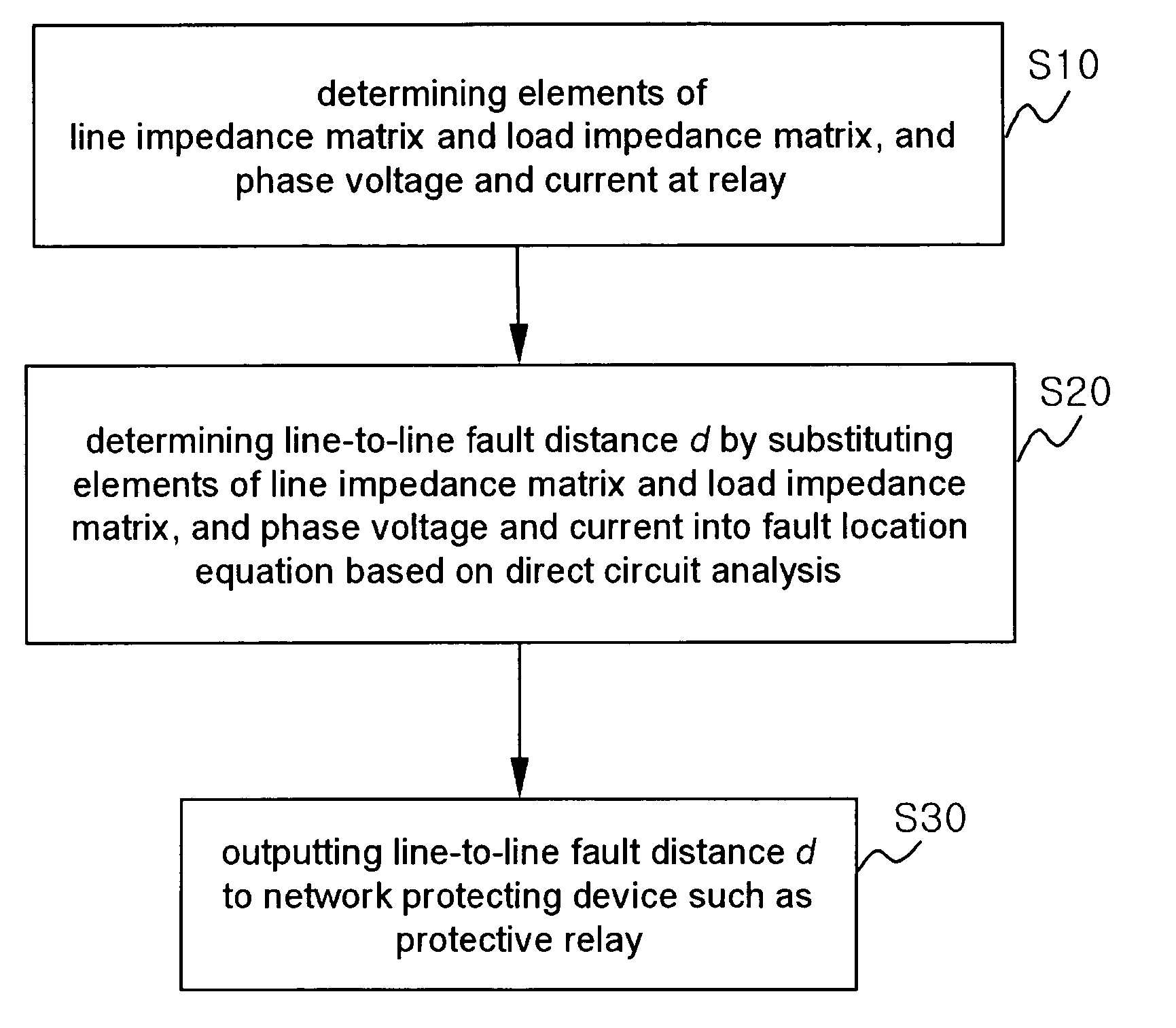
Figure 1 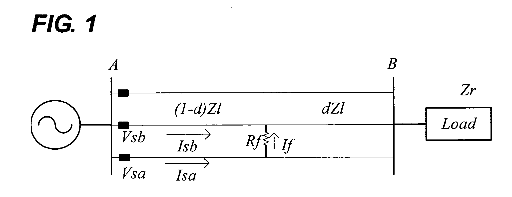
Figure 2 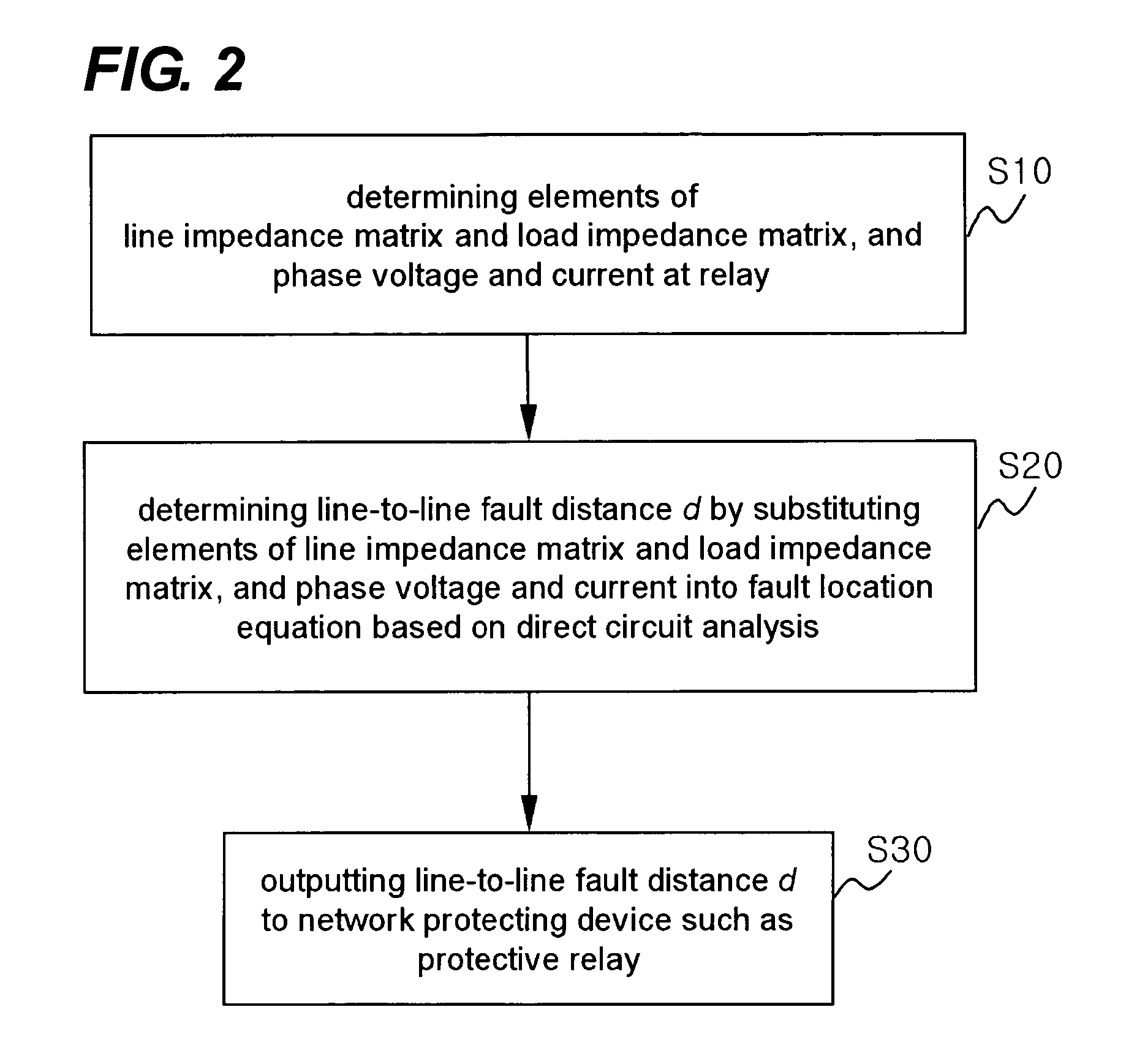
Figure 3
Abstract
Description
BACKGROUND OF THE INVENTION
[0001] (a) Field of the Invention
[0002] The present invention relates to a method for detecting a line-to-line fault location in power network, and more particularly, detecting the line-to-line fault location with direct 3-phase circuit analysis without using a symmetrical component transformation, whereby even in an unbalanced 3-phase circuit the line-to-line fault location can be accurately detected.
[0003] (b) Description of the Related Art
[0004] Rapid growth of economy has resulted in large scale of power systems, and an excessive increase in transmission and distribution networks of electric power systems causes many kinds of faults by various causes. Transmission and distribution networks of electric power systems are playing very important roles as the links between the power suppliers and the consumers. However, because most of lines are exposed to air, lightning, contact of animals or mal-functioning of protection devices causes many kinds of faults. W...
Examples
Embodiment Construction
[0026]Preferred embodiment of the present invention will now be described in detail, with reference to the accompanying drawings.
[0027]FIG. 1 shows general 3-phase transmission and distribution of simplified diagram of faulted network whether they are operated in a balance or unbalance manner. The proposed algorithm use voltages and currents measured at a relay.
[0028]Based on a model shown in FIG. 1 and assuming the capacitance of lines negligible, phase voltages and phase currents at the location of relay A satisfy the following model equation.
VSa−VSb=(1−d)((Zlaa−Zlba)Isb+(Zlac−Zlbb)Isb +(Zlac−Zlcb)+IfRf (1)
[0029]Where, VSa and VSb are phase voltages of a-phase and b-phase respectively, and ISa, ISb and ISc are phase currents of a-phase, b-phase and c-phase respectively at the relay A, ISabc=[ISa ISb ISc]′ is a phase current vector at the relay A, Zlabc=[ZlaaZlabZlacZlbaZlbbZlbcZlcaZlcbZlcc]
represents a line impedance matrix, If represents a fault current, Rf is a fault resistance...