
Method and device for multi photon excitation of a sample
Patent Information
- Authority / Receiving Office
- US · United States
- Current Assignee / Owner
- Publication Date
- 2006-10-03
- Estimated Expiration
- Not applicable · inactive patent
Smart Images
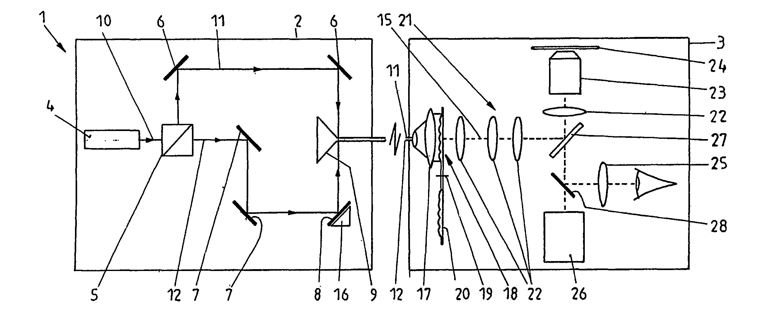
Figure 1 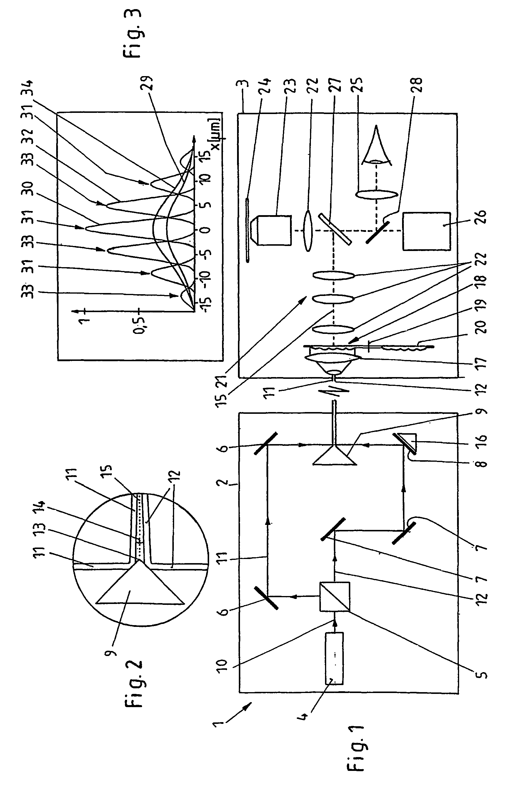
Figure 2 
Figure 3
Abstract
Description
CROSS REFERENCE TO RELATED APPLICATIONS
[0001] This application is a continuation in part of International Patent Application PCT / EP02 / 03785 filed Apr. 5, 2002 and claiming priority to co-pending German Patent Application No. 101 18 355.0-42 filed Apr. 12, 2001 both of which are entitled “Verfahren und Vorrichtung zur Mehrphotonenanregung einer Probe”.FIELD OF THE INVENTION
[0002] The present invention generally relates to a method for multi photon excitation of a sample, comprising the steps of splitting a laser beam into at least two coherent partial beams each having a beam axis and a same intensity distribution about its beam axis, directing the partial beams in different directions, and projecting the partial beams from different directions onto a common measuring plane running transversely to the beam axes, an interference pattern being formed by the coherent partial beams in the area of the measuring plane.
[0003] Further, the invention relates to a device for multi photon excitati...
Examples
Embodiment Construction
[0035]Referring now in greater detail to the drawings, the device 1 shown in FIG. 1 consists of two partial arrangements 2 and 3, the areas of which are each enclosed by a line in the present drawing. This does, however, not mean that the partial arrangements 2 and 3 have to be placed in different housings, or that there has to be another spatial or physical separation. The subdivision of the device 1 into the partial arrangements 2 and 3 only relates to their function.
[0036]The partial arrangements 2 of the device 1 includes a laser 4, a beam splitter 5, deviation mirrors 6, 7 and 8, and a roof mirror 9. The laser 4 emits a coherent laser beam 10. The beam splitter 5 splits the laser beam 10 into two partial beams 11 and 12 which are coherent with regard to each other and which each have a same intensity distribution about their beam axes. The partial beams 11 und 12 are deviated by means of the deviation mirrors 6 to 8, and they are directed towards the roof ridge 13 of the roof m...