
Light-emitting device
a technology of light-emitting devices and light-emitting lamps, which is applied in the direction of semiconductor devices for light sources, lighting and heating apparatus, and lighting support devices, etc., can solve the problems of affecting the eyesight of users, mercury elements inside fluorescent lamps may be harmful to the human body, and pollute the environment, so as to achieve the effect of large total light throughput and even light emission
Patent Information
- Authority / Receiving Office
- US · United States
- Patent Type
- Patents(United States)
- Current Assignee / Owner
- Publication Date
- 2008-02-19
- Estimated Expiration
- Not applicable · inactive patent
Smart Images
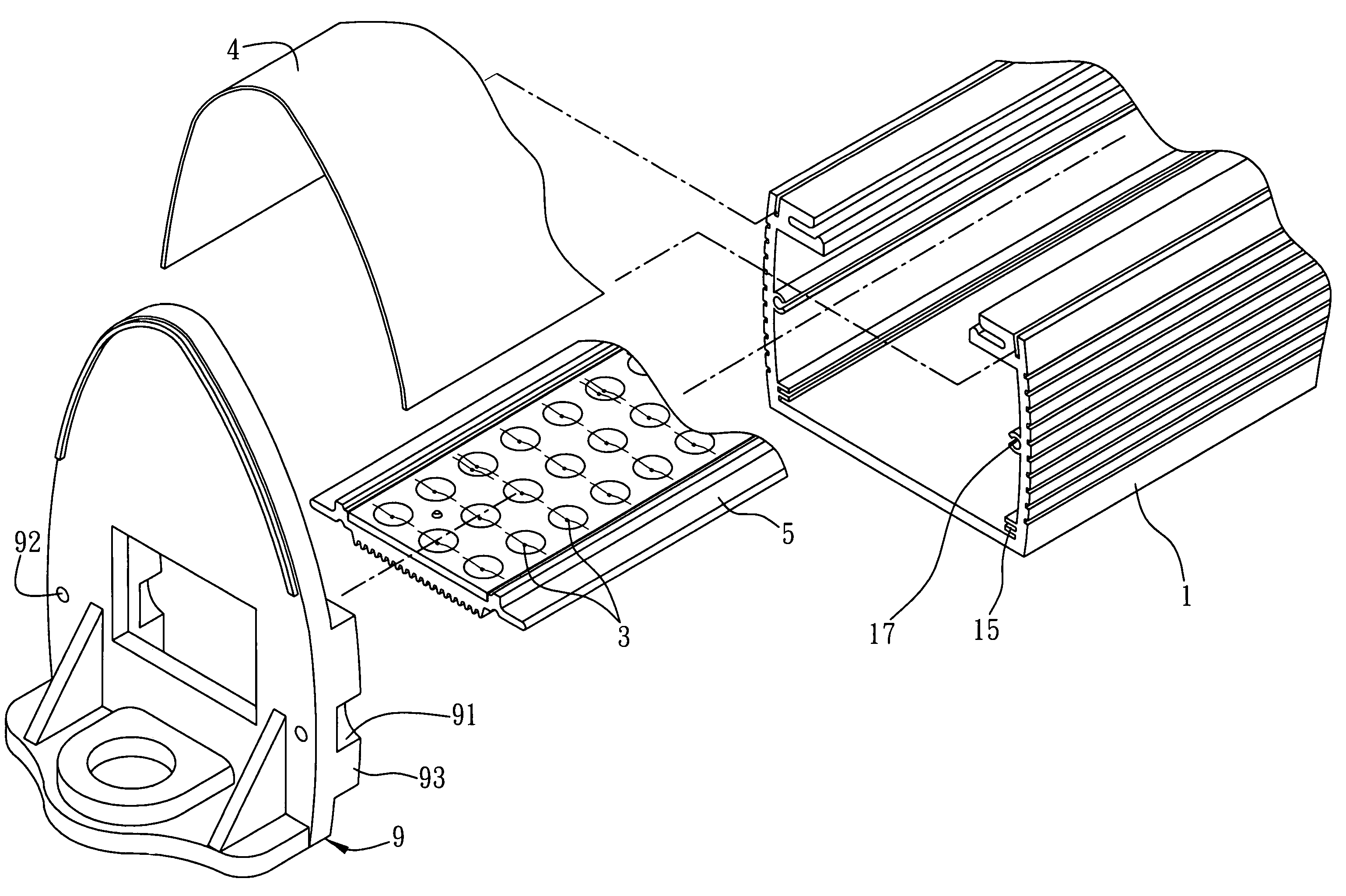
Figure 1 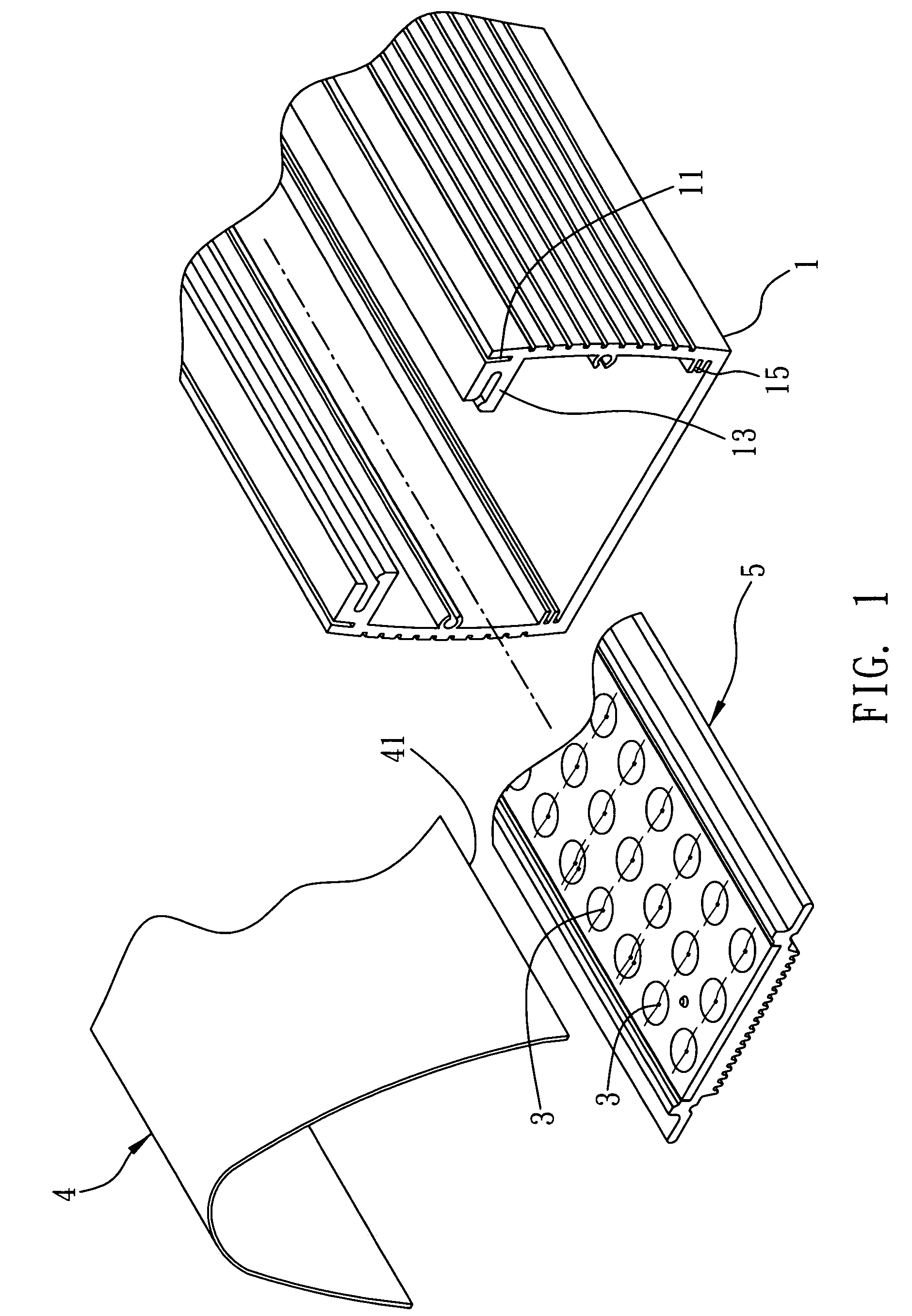
Figure 2 
Figure 3
Abstract
Description
FIELD OF THE INVENTION
[0001] The present invention relates to an illuminating technique, and more particularly, to a light-emitting device with a plurality of light-emitting elements.BACKGROUND OF THE INVENTION
[0002] Traditional illumination usually uses fluorescent lamps as the light source, which allows high speed electrons in argon or neon gas to excite mercury by collision to produce ultraviolet light. The ultraviolet, when strikes a phosphor powder coated in the lamps, emits visible fluorescence for illumination. Since light source provided by this kind of illumination varies with AC current, flickering of the light source may directly affect the users' eyesight. Additionally, the mercury element inside the fluorescent lamps may be harmful to the human bodies. Disposing of the fluorescent lamps may also pollute the environment. Furthermore, applications of this type of lightings require electronic ballast or high-frequency inverter. It also has the shortcomings of slow starting,...
Examples
first embodiment
[0030]FIGS. 1 to 5 are diagrams depicting a first embodiment of the light-emitting device of the present invention. Referring to FIG. 1, an exploded diagram of the first embodiment of the light-emitting device of the present invention is shown. The light-emitting device of the present invention comprises a body 1, a plurality of light-emitting elements 3 at a side of the body 1 and an optical processing element 4 at a side of the light-emitting elements 3.
[0031]A first joining part 11 is provided at a side of the body 1 for joining with the optical processing element 4. In this embodiment, the body is a hollow frame and the first joining part 11 can, for example, be a track. Meanwhile, the body 1 further comprises a third joining part 13 that can also be, for example, a track. The third joining part 13 is substantially perpendicular to the first joining part 11.
[0032]The light-emitting elements 3 are disposed at the side of the body having the first joining part 11 for emitting ligh...
second embodiment
[0042]FIGS. 6 and 7 are diagrams depicting a second embodiment of the light-emitting device of the present invention. Elements that are similar or equal to those shown in the first embodiment are denoted with similar to equal reference numbers, and their description are omitted in order not to obscure the understanding of the present invention.
[0043]The main difference of the present embodiment and the second embodiment is that a fastening element is added in the present embodiment.
[0044]As shown in FIG. 6, the body1 further comprises a seventh joining portion 17, such as a track. A fastening element 9 is disposed at one side of the body 1, which can be an end cap, for example. The fastening element 9 comprises an eighth joining portion 91 corresponding to the seventh joining portion 17, a through hole 92 in the eighth joining portion 91 and a ninth joining portion 93 located next to the eighth joining portion 91. The eighth joining portion 91 is, for example, an arc indentation to ...