
Tunable capacitively-loaded magnetic dipole antenna
a capacitively loaded, magnetic dipole antenna technology, applied in the direction of resonant antennas, antenna supports/mountings, electrically long antennas, etc., can solve the problem that both feeds are likely to pick up the same noise, and achieve the effect of reducing the amount of current circulating, reducing the susceptibility of counterpoise, and less susceptible to rf nois
Patent Information
- Authority / Receiving Office
- US · United States
- Current Assignee / Owner
- Publication Date
- 2008-08-05
- Estimated Expiration
- Not applicable · inactive patent
Smart Images
Figure 1 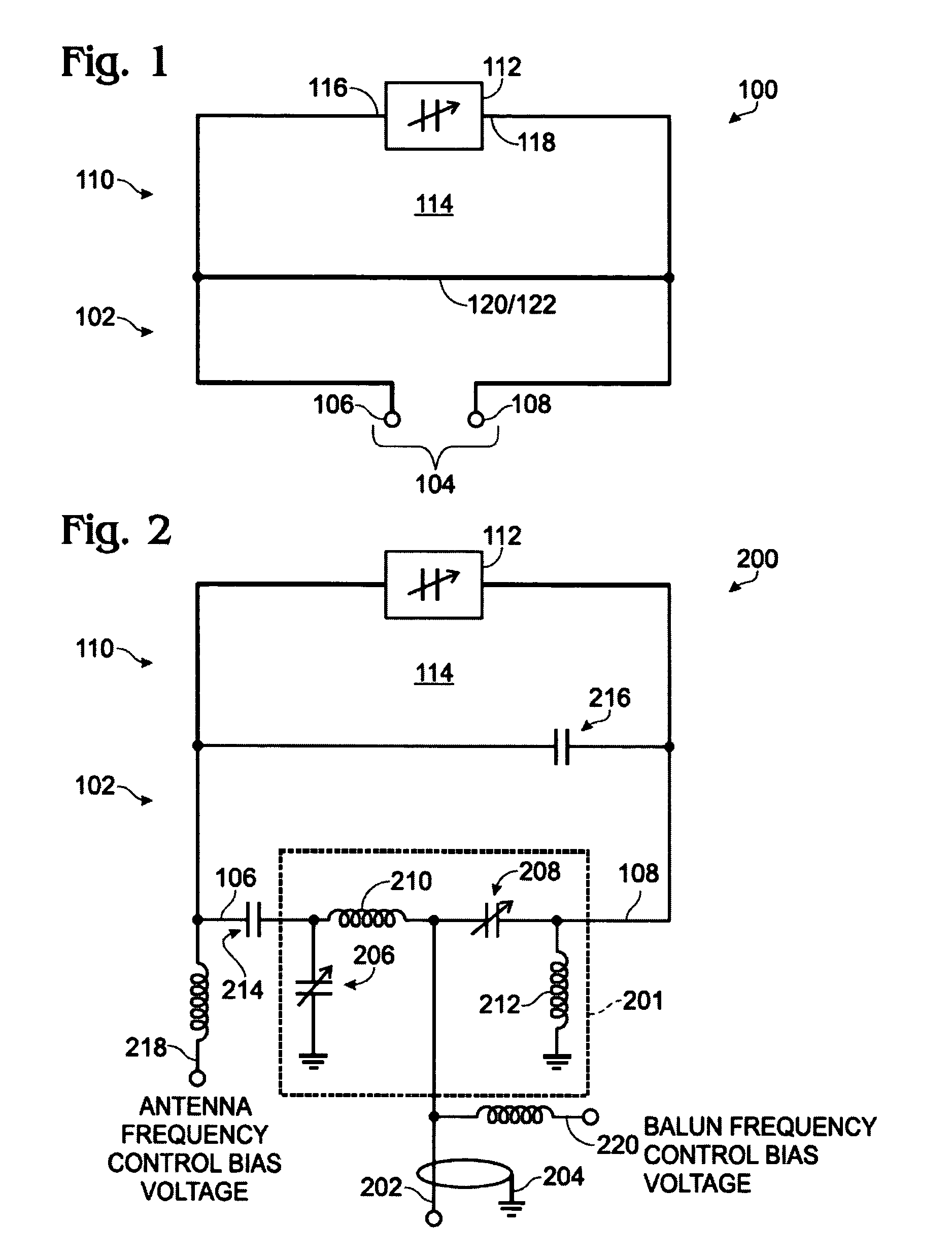
Figure 2 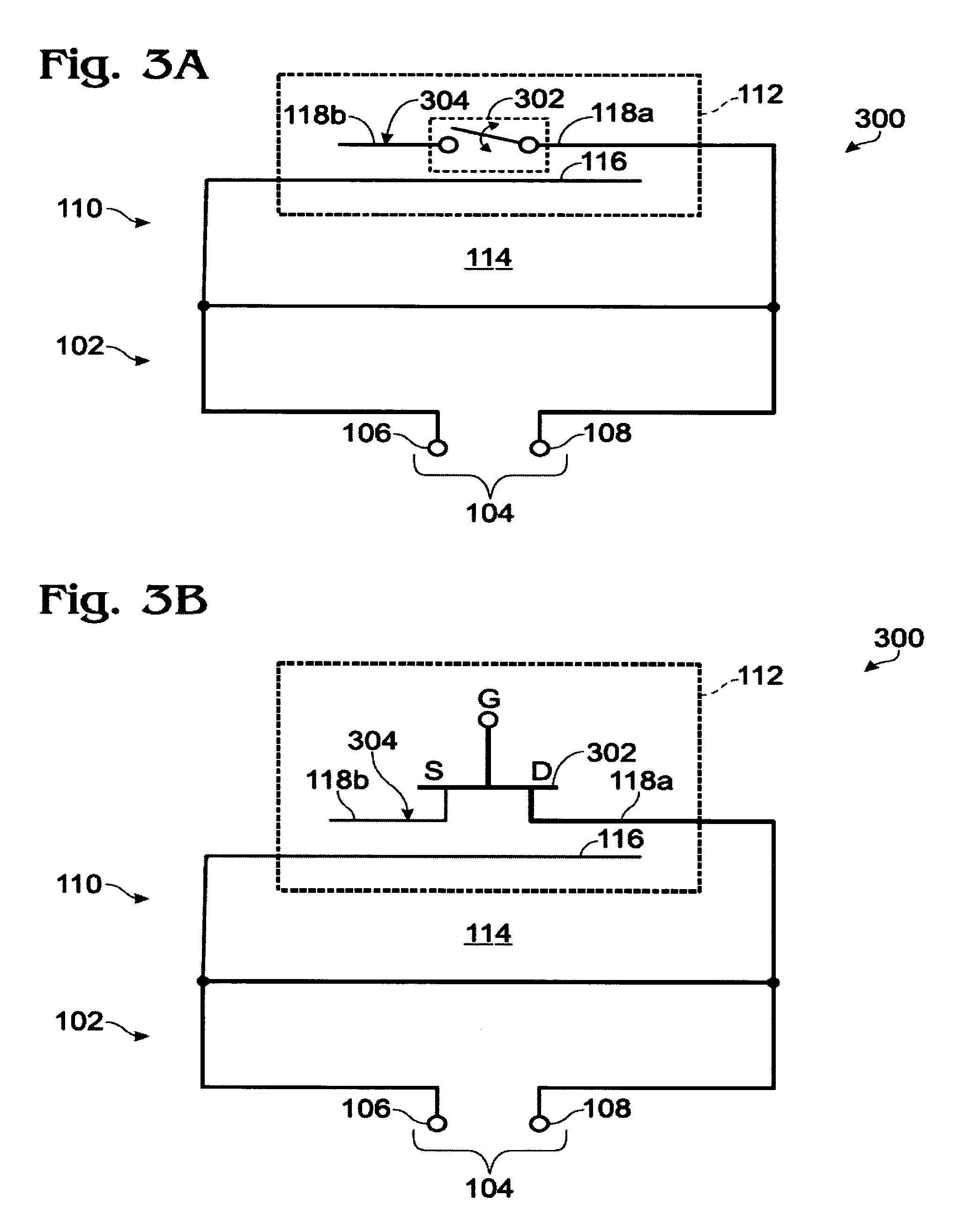
Figure 3
Abstract
Description
RELATED APPLICATIONS
[0001] This application is a continuation-in-part of application Ser. No. 10 / 940,935, filed Sep. 14, 2004 now U.S. Pat. No. 7,239,290, the disclosure of which is incorporated herein by reference.FIELD OF THE INVENTION
[0002] This invention generally relates to wireless communications and, more particularly, to a tunable capacitively-loaded magnetic dipole antenna.BACKGROUND OF THE INVENTION
[0003] The size of portable wireless communications devices, such as telephones, continues to shrink, even as more functionality is added. As a result, the designers must increase the performance of components or device subsystems and reduce their size, while packaging these components in inconvenient locations. One such critical component is the wireless communications antenna. This antenna may be connected to a telephone transceiver, for example, or a global positioning system (GPS) receiver.
[0004] State-of-the-art wireless telephones are expected to operate in a number of differe...
Examples
Embodiment Construction
[0021]FIG. 1 is a plan view of a frequency-tunable capacitively-loaded magnetic dipole antenna. The antenna 100 comprises a transformer loop 102 having a balanced feed interface 104. The balanced feed interface 104 accepts a positive signal on line 106 and a negative signal (considered with respect to the positive signal) on line 108. In some aspects, the signal on line 108 is 180 degrees out of phase with the signal on line 106. The antenna 100 also comprises a capacitively-loaded magnetic dipole radiator 110, having a tunable (variable) effective electrical length. The effective electrical length is related to the physical length of the radiator 110, and subject to the influence of the adjacent dielectric through which the magnetic radiation propagates.
[0022]In one aspect, the capacitively-loaded magnetic dipole radiator 110 comprises an electric field bridge 112. If enabled as a dielectric gap, or lumped element capacitor for example, the electric field across the bridge 112 rema...