
Gas turbine engine having a multi-variable closed loop controller for regulating tip clearance
a closed loop controller and gas turbine engine technology, applied in the direction of machines/engines, leakage prevention, mechanical equipment, etc., can solve the problems of reducing the tip clearance of the rotor blade, not returning a full measure of work to the operation of the turbine, and increasing the associated loss of engine efficiency, so as to increase the efficiency of the engine
Patent Information
- Authority / Receiving Office
- US · United States
- Patent Type
- Patents(United States)
- Current Assignee / Owner
- Publication Date
- 2016-02-09
Smart Images
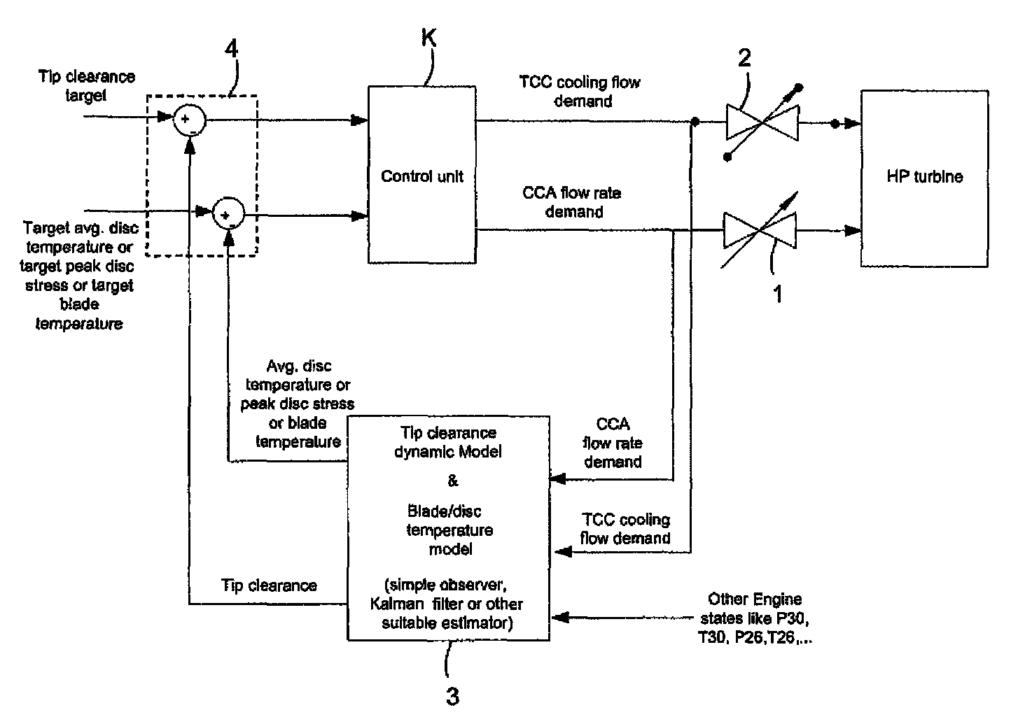
Figure 1 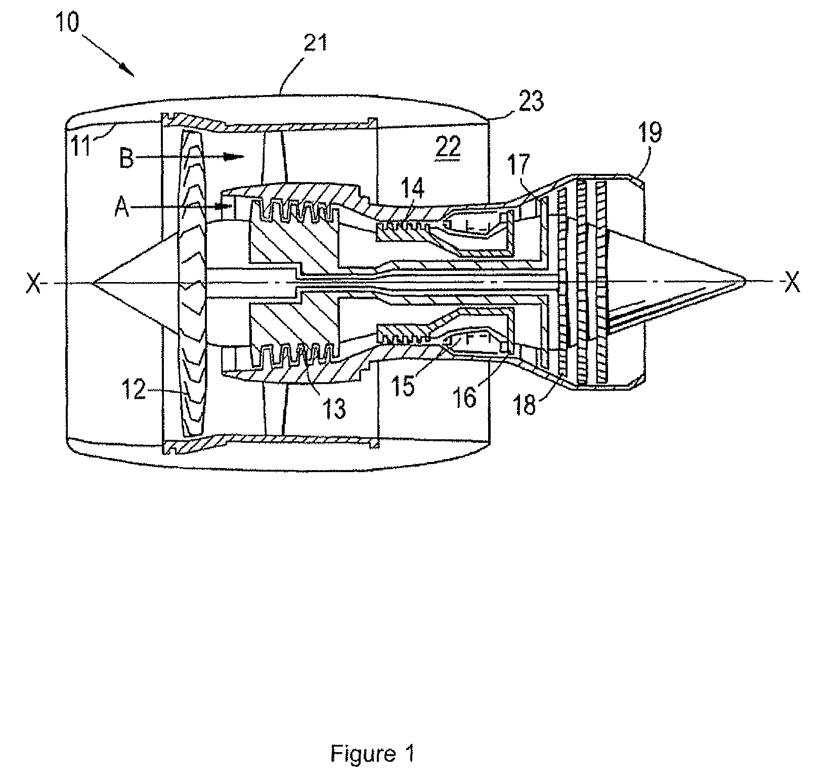
Figure 2 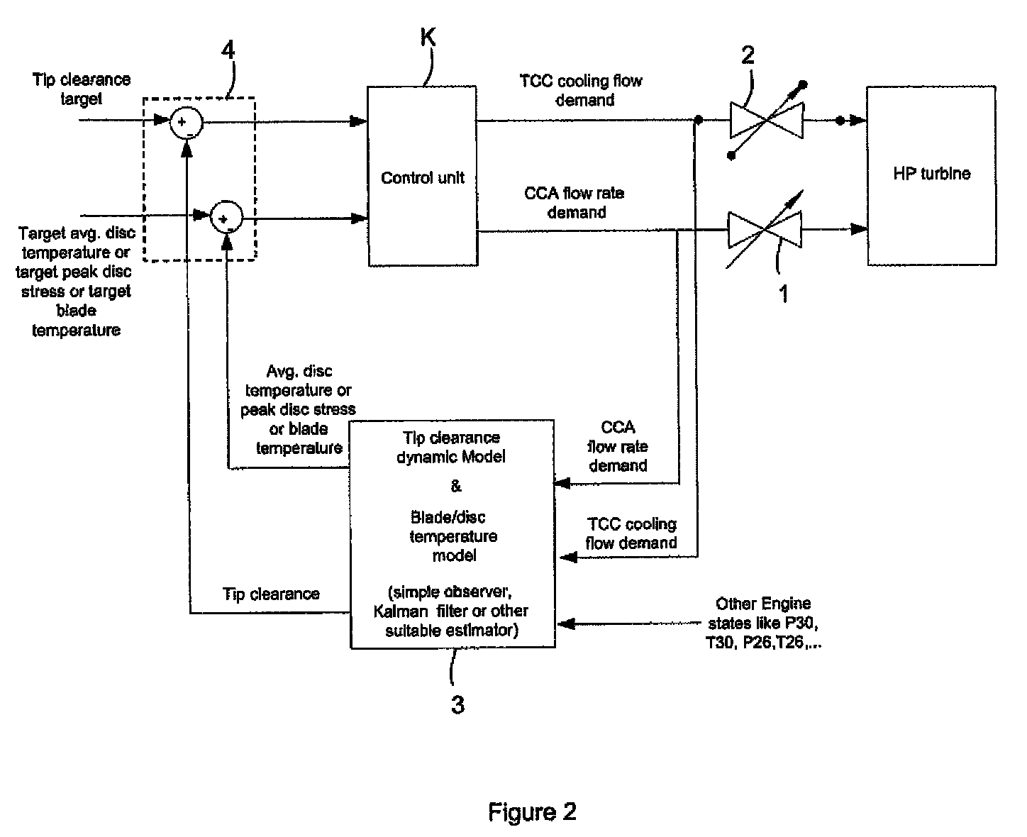
Figure 3
Abstract
Description
FIELD OF THE INVENTION
[0001] The present invention relates to a closed-loop controller, and, in particular, to a gas turbine engine having a system including such a controller for cooling the turbine section of the gas turbine and for providing tip clearance control.BACKGROUND OF THE INVENTION
[0002] With reference to FIG. 1, a ducted fan gas turbine engine generally indicated at 10 has a principal and rotational axis X-X. The engine comprises, in axial flow series, an air intake 11, a propulsive fan 12, an intermediate pressure compressor 13, a high-pressure compressor 14, combustion equipment 15, a high-pressure turbine 16, and intermediate pressure turbine 17, a low-pressure turbine 18 and a core engine exhaust nozzle 19. A nacelle 21 generally surrounds the engine 10 and defines the intake 11, a bypass duct 22 and a bypass exhaust nozzle 23.
[0003] The gas turbine engine 10 works in a conventional manner so that air entering the intake 11 is accelerated by the fan 12 to produce two a...
Examples
first embodiment
[0053]FIG. 2 shows schematically a system for cooling the high pressure turbine of a gas turbine engine and for providing tip clearance control in the high pressure turbine. The system includes a closed-loop control unit K which is a multivariable controller acting on error variables, s. The control unit embodies a gain matrix, K(s), of the form:
[0054]K(s)=[K11(s)K12(s)K21(s)K22(s)]
to produce a cooled cooling air (CCA) flow rate demand signal and a turbine clearance control (TCC) flow demand signal which are issued to respectively a valve 1 of a turbine section cooling sub-system and a valve 2 of a tip clearance control sub-system. The valves can be, for example, switched vortex valve of the type described in U.S. Pat. No. 3,267,946.
[0055]The gain matrix allows independencies between the CCA and TCC sub-systems to be introduced. The gain matrix can be determined, for example, by a robust control methodology, simple decoupled PI control laws, a linear quadratic regulator contro...
third embodiment
[0064]An alternative to estimating the observer variables is to provide closed-loop control which uses actual variable measurements. FIG. 4 shows schematically a system which implements this approach. A pyrometer and a tip clearance sensor respectively provide measurements of average disc temperature and tip clearance. These measurements are then the observer variables which are sent to the comparator 4 for comparison with respectively a target average disc temperature and a target tip clearance.
[0065]Another option is to adopt the modelling approach for e.g. disc / blade temperature or disc stress and adopt the measurement approach for tip clearance, or vice versa. Indeed, it is possible to improve the accuracy of the observer unit 3 by supplementing the modelling approach of e.g. the first or second embodiment with the direct measurement approach of the third embodiment.