Supercharge Your Innovation With Domain-Expert AI Agents!

Voltage converter using mos transistors

A technology of voltage converters and transistors, which is applied in the direction of conversion equipment, electrical components, and electronic switches without intermediate conversion to AC, and can solve problems such as the inability to guarantee a constant noise level

Inactive Publication Date: 2008-04-16
NXP BV
View PDF3 Cites 0 Cited by
  • Summary
  • Abstract
  • Description
  • Claims
  • Application Information

AI Technical Summary

Problems solved by technology

[0019] Therefore, with this voltage converter, the noise level cannot be guaranteed to be at a constant level when the input voltage VDD varies, even if VDD changes only very slightly
[0020] The technical limitations of such prior art converters are particularly vexing for the need to meet EMC standards

Method used


Image

  • Voltage converter using mos transistors
  • Voltage converter using mos transistors
  • Voltage converter using mos transistors

Examples


Embodiment Construction

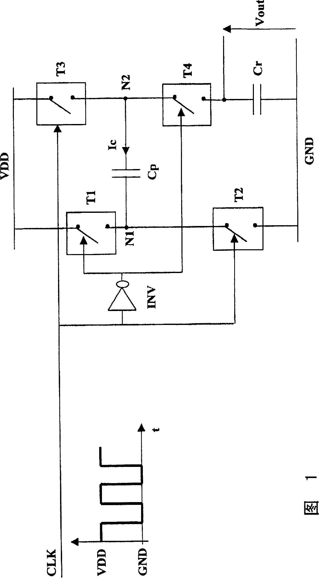
[0053] Figure 2 shows a voltage converter according to the invention. This converter is based on the same working principle of the prior art voltage converter described with reference to FIG. 1 .

[0054]For this, the converter shown in Fig. 2 uses MOS type transistors T1-T2-T3-T4 as switches. Transistors T1-T3-T4 are of P-MOS type and transistor T2 is of N-MOS type.

[0055] While transistors T2-T3 are equivalent to closed switches, transistors T1-T4 are equivalent to open switches. Conversely, while transistors T2-T3 are equivalent to open switches, transistors T1-T4 are equivalent to closed switches. According to the beat of the clock signal CLK, the state changes of the transistors T1-T2-T3-T4 used as switches are realized.

[0056] The switching cycle of the transistors T1-T2-T3-T4 allows the charging of the capacitor Cp when the transistors T2-T3 are equivalent to closed switches, so as to supply the Level output voltage Vout.

[0057] The transistors T1-T2-T3 are c...


PUM


Abstract

The invention relates to a voltage converter for generating an output voltage at an output terminal from an input voltage VDD taken from ground GND, said voltage converter comprising a switched capacitance Cp arranged in a bridge of transistors of the MOS type functioning as switches, each transistor being controlled by a control signal having a level varying in the rhythm of a clock signal clock. The invention is characterized in that the converter comprises at least a control circuit for supplying said control signal applied between the gate and the source of one of the transistors functioning as a switch, said control circuit having the particular function of generating a control signal having an amplitude which is inversely proportional to the input voltage VDD when the transistor which it controls is equivalent to a closed switch.

Description

technical field [0001] The invention relates to a voltage converter for generating an output voltage at an output from an input voltage VDD taken from ground GND, said voltage converter comprising: [0002] - a capacitance Cp having a first terminal N1 and a second terminal N2, [0003] - four MOS type transistors T1-T2-T3-T4 used as switches, each transistor is controlled by a control signal having a level that changes according to the clock signal beat, each transistor includes a source, a gate, a drain, And so that the first transistor T1 is connected between the input voltage VDD and the first terminal N1, the second transistor T2 is connected between the first terminal N1 and the ground GND, and the third transistor T3 is connected between the input voltage VDD and the second terminal N2 between, and the fourth transistor T4 is connected between the second terminal N2 and the output terminal, [0004] The invention has numerous applications in electronic equipment with ...

Claims


Application Information

Patent Timeline
Patent Type & Authority Patents(China)
IPC IPC(8): H02M3/07H03K17/16
CPCH02M3/07
Inventor E·于冈
Owner NXP BV
Features
  • R&D
  • Intellectual Property
  • Life Sciences
  • Materials
  • Tech Scout
  • Unparalleled Data Quality
  • Higher Quality Content
  • 60% Fewer Hallucinations
Learn More