Lamp head conversion device

A technology of conversion device and lamp head, which is applied in the field of lighting decoration, can solve problems such as difficulty in assembling springs, increased material costs, and low production efficiency, and achieves the effect of easy production and assembly and simple structure

Inactive Publication Date: 2008-06-18
GUANGZHOU GOLD ELECTRIC LIGHTING
View PDF5 Cites 0 Cited by
  • Summary
  • Abstract
  • Description
  • Claims
  • Application Information

AI Technical Summary

Problems solved by technology

However, it is very difficult to assemble components such as springs, guide rails, and locks in the small conversion unit, resulting in low production efficiency and increased material costs

Method used


Image

  • Lamp head conversion device
  • Lamp head conversion device
  • Lamp head conversion device

Examples


Embodiment Construction

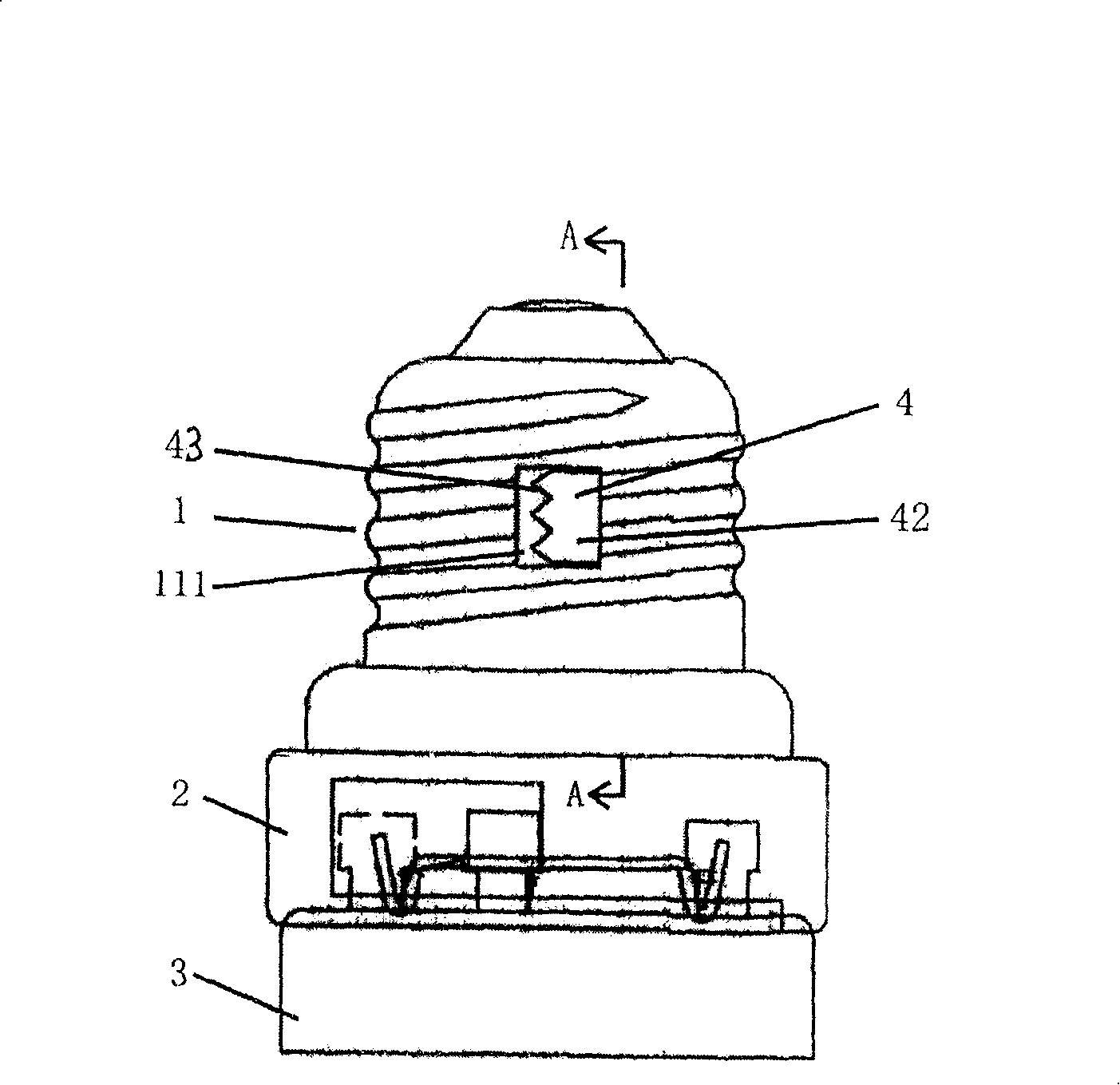
[0014] Such as figure 1 , 2 As shown, the present invention is a lamp cap conversion device, one end of which is a plug portion 2 suitable for the pins of an energy-saving lamp 3, and the other end is a threaded portion 1 screwed to a screw socket. An elastic pressure piece 4 for fixing and locking the lamp cap conversion device and the lamp holder to prevent the lamp cap conversion device from reversing is fixedly installed on the surface of the threaded part 1 along the thread direction.

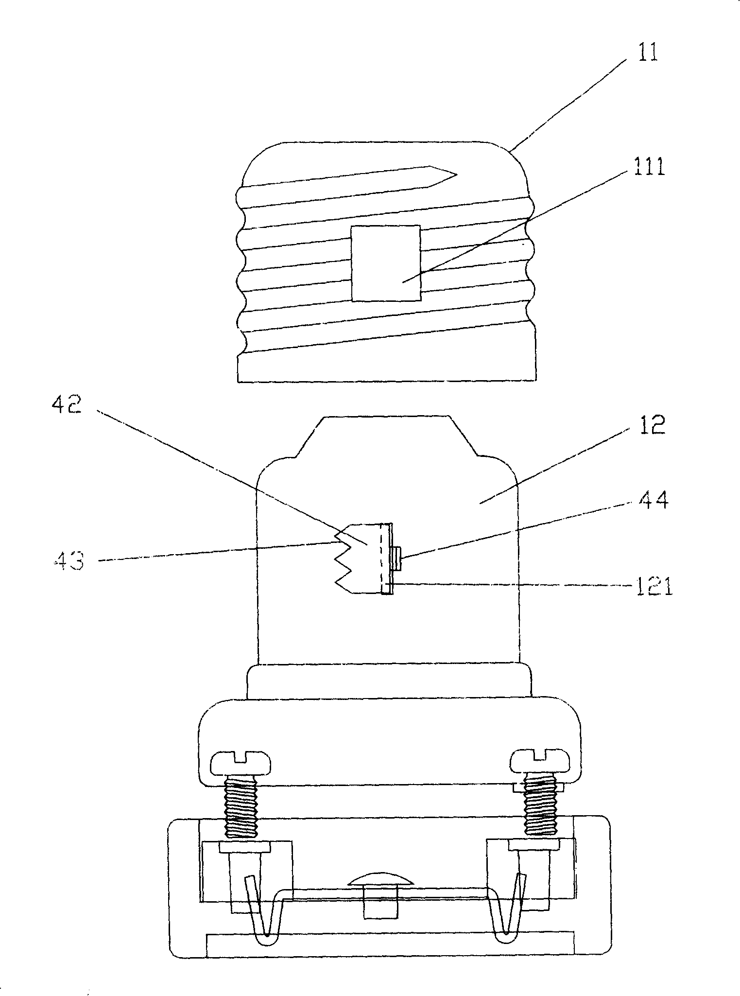
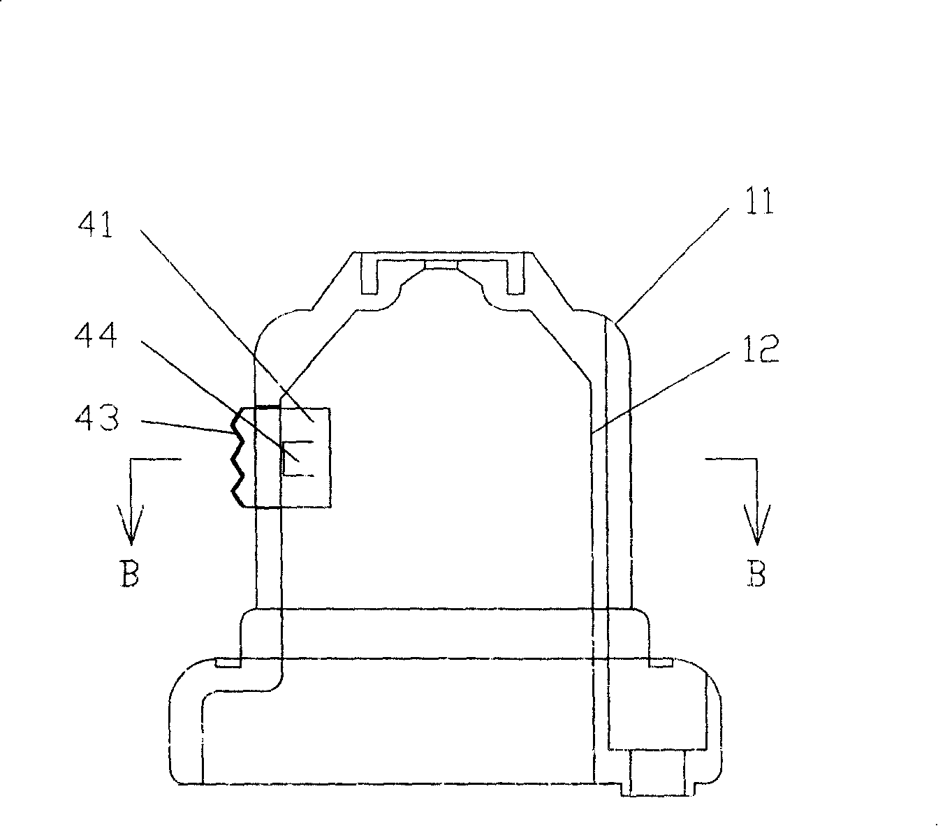
[0015] Such as figure 2 , 3 As shown, the threaded portion 1 has a double-layer structure, including a threaded conductive outer layer 11 and an insulating inner layer 12 . The surface of the insulating inner layer 12 is provided with a mounting groove 121 perpendicular to the thread direction, and the threaded conductive outer layer 11 is provided with an opening 111 , and the mounting groove 121 corresponds to a side of the opening 111 .

[0016] Such as image 3 , 4 As shown, one...


PUM


Abstract

The improved transfer device for lamp holder comprises a plug part on one end and a screw-thread part on another end to screw with lamp socket. Wherein, arranging a spring pressing piece to grip with out socket inner screw and prevent inversion, and an opening on screw surface to accommodate the piece. This invention is simple and convenient to assembly for large-batch production, and benefit to continue using energy-saving lamp.

Description

technical field [0001] The invention relates to the field of lamp decorations, in particular to a lamp cap conversion device. Background technique [0002] The installation method of compact fluorescent lamps currently on the market is clamping, and the two clamping feet are columnar, and the diameter of the head is larger than that of the column body. The special lamp holder for fluorescent lamps includes two sockets, the sockets are arc-shaped, symmetrically arranged on the circle centered on the axis of the lamp holder, the diameter of the insertion end of the socket is larger than the head of the clamping foot, and the diameter of the clamping end is smaller than that of the clamping foot head. When the clamping foot of the fluorescent lamp is inserted into the socket from the insertion end and rotates along the socket to the clamping end, the head of the clamping foot can be locked and cannot be released. [0003] And general ordinary lamp holder is only applicable to...

Claims


Application Information

Patent Timeline
Patent Type & Authority Patents(China)
IPC IPC(8): H01R33/94H01R33/22
Inventor 林家鹳
Owner GUANGZHOU GOLD ELECTRIC LIGHTING
Why Eureka
Try Eureka