
Automatic cleaning trolley for lawn garbage
A technology for automatic cleaning and garbage, which is applied to lawn growth, horticulture, botany equipment and methods, etc., can solve the problems of low automation, high labor intensity, and low efficiency, achieve high speed, improve work efficiency, and eliminate electricity consumption. cost effect
- Summary
- Abstract
- Description
- Claims
- Application Information
AI Technical Summary
Problems solved by technology
Method used
Image

Examples
Embodiment Construction
[0016] The present invention will be further described below in conjunction with specific embodiments. The exemplary embodiments and descriptions of the present invention are used to explain the present invention, but not as a limitation to the present invention.
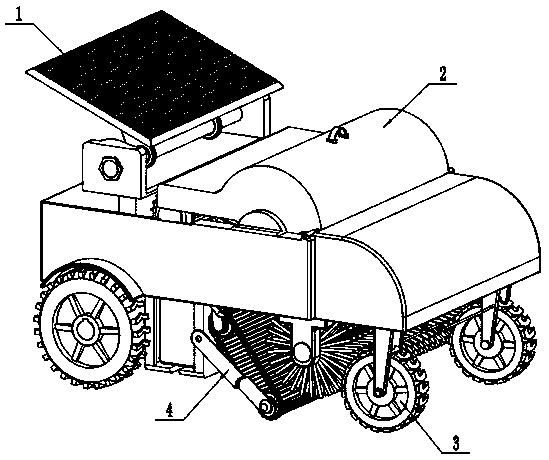
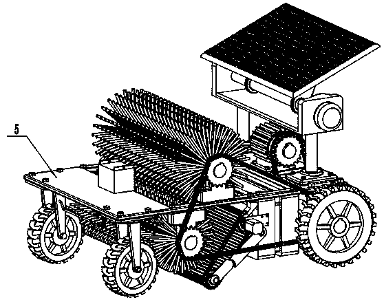
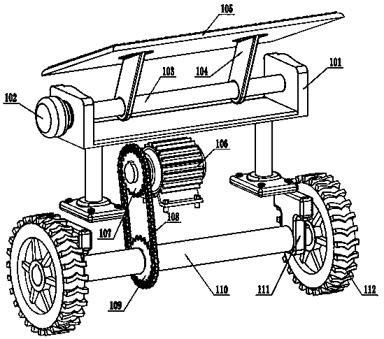
[0017] Such as figure 1 , figure 2 , image 3 , Figure 4 , Figure 5 A lawn garbage automatic cleaning trolley shown includes a drive unit 1, an outer cover 2, a steering detection unit 3, a cleaning unit 4, and a main mounting plate 5. The driving unit 1 is installed on the rear end of the main mounting plate 5, and the steering detection unit 3 Installed on the front end of the main mounting plate 5 , the cleaning unit 4 is installed in the middle of the main mounting plate 5 , and the outer cover 2 is fixed above the main mounting plate 5 .
[0018] The drive unit 1 includes a solar mounting frame 101, a first motor 102, a first transmission shaft 103, a panel support 104, a solar panel 105, a second motor ...
PUM
 Abstract
Description
Claims
Application Information