High performance composite shock absorber

A technology of shock absorbers and dampers, which is applied in the direction of shock absorbers, springs/shock absorbers, shock absorbers, etc., can solve problems such as non-smooth hysteresis curves, restricting the application of dampers, and easy leakage, etc. The perfusion is not dense, with self-limiting ability, and the effect of solving the leakage problem

Inactive Publication Date: 2008-07-02
SOUTHEAST UNIV
View PDF4 Cites 0 Cited by
  • Summary
  • Abstract
  • Description
  • Claims
  • Application Information

AI Technical Summary

Problems solved by technology

Viscoelastic dampers are cheap to manufacture and have strong energy dissipation capabilities, but their performance is greatly affected by the ambient temperature
Metal dampers and friction dampers are easy to manufacture and low in cost, but their hysteresis curves are not smooth, and it is difficult to achieve unity in their better recovery ability and higher energy dissipation capacity.
Shape memory alloy dampers are expensive and highly temperature dependent
Viscous fluid dampers and magneto (electric) rheological dampers use the movement of viscous fluids and magneto (electric) rheological bodies to dissipate vibration energy. However, the main disadvantages of this damper include: (1) viscous fluid and The magnetic (electric) rheological body is easy to leak; (2) the cost of using a large number of viscous fluid and magnetic (electrical) rheological body is expensive; (3) the viscous fluid damper and the magnetic (electrical) rheological damper cannot provide Give the structure enough rigidity; (4) In the process of perfusing viscous fluid and magneto (electric) rheological body, the perfusion is not dense, and it is easy to generate air bubbles, which leads to the necking phenomenon of the energy consumption curve
The shortcomings of these dampers seriously restrict the application of various dampers in civil vibration reduction engineering.

Method used


Image

  • High performance composite shock absorber

Examples


Embodiment Construction

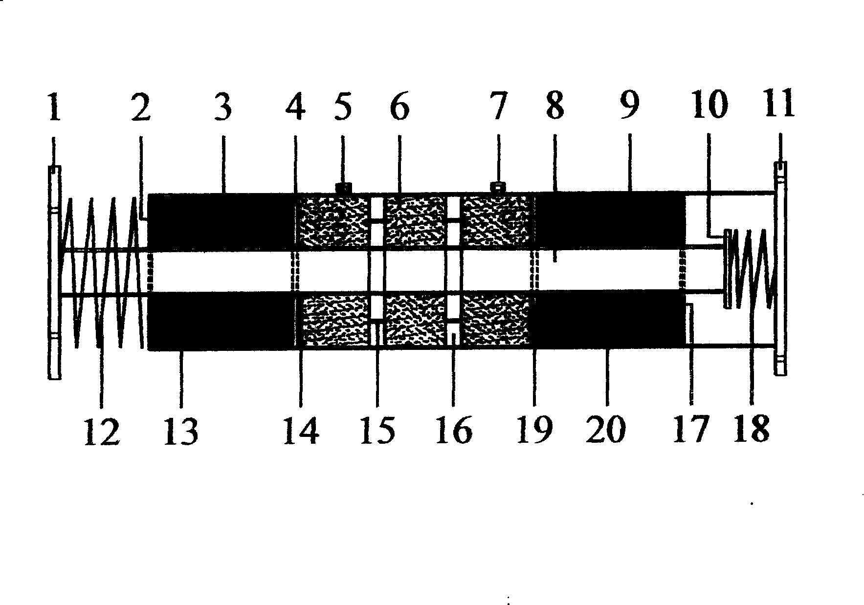
[0009] In the composite shock absorber of the present invention, the inner steel pipe 8 is located in the outer steel pipe 9, the left end of the inner steel pipe 8 extends out of the outer steel pipe 9, the left end of the inner steel pipe 8 is fixed with a left connecting steel plate 1, and the left end of the outer steel pipe 9 is fixed with an outer steel pipe End plate 2, a left spring 12 is arranged between the outer steel pipe end plate 2 and the left connecting steel plate 1; A right spring 18 is provided between the plate 10 and the right connecting steel plate 11; an inner sealing plate 17 is provided in the inner hole at the right end of the outer steel pipe 9, and a cavity dividing plate is fixed in the outer steel tube 9; between the left cavity dividing plate 4 and the outer An ellipsoidal protrusion 3 is fixed on the inner steel pipe 8 between the end plates 2 of the steel pipes, and is poured with Lead 13; An ellipsoidal protrusion 20 is fixed on the inner stee...


PUM


Abstract

High complex absorber which is used in civil engineering structure absorption of vibration. The interior and exterior steel pipe surrounded by the absorber consists of three parts, the central cavity is liquid amortisseur, and the side cavitys are lead amortisseur. On the left of the interior steel pipe, there fixes a board, on the right is the controlling board. On the left of the exterior steel pipe is fixed the inner board, on the right there respectively fixes the left and right ellipsoidal bulges between the left cavity baffle plate and the interior steel pipe and on the interior steel pip between the right baffle plate and the inner sealed plate. On the ellipsoidal bulges there is exterior perfusion lead, there are sealing port and pouring port in the central exterior wall of the exterior steel pipe, on the interior steel pipe is welded a moving valve in which there is a liquor tube and between the left cavity baffle plate and right cavity baffle plate is he perfusion liquor.

Description

technical field [0001] The invention is an anti-vibration (shock) device for civil engineering structures, in particular a composite shock absorber. Background technique [0002] Earthquake force and wind vibration force are the main control loads borne by the building structure, and are also the main factors leading to the damage and collapse of the building structure. Accurately understand the force mechanism and dynamic response of the structure under the action of dynamic load, and implement reliable measures for it. Anti-vibration (earthquake) protection measures are a frontier research topic. Structural energy dissipation and vibration reduction control is a new type of anti-vibration (seismic) method, that is, using energy dissipation and vibration reduction devices to consume external excitation energy, so as to reduce the damage of external excitation to the main structure. At present, energy-dissipating vibration damping devices developed and researched for wind v...

Claims


Application Information

Patent Timeline
Patent Type & Authority Patents(China)
IPC IPC(8): E04B1/98F16F9/00
Inventor 徐赵东李爱群
Owner SOUTHEAST UNIV
Why Eureka
Try Eureka