Method of manufacturing outer ring member for constant velocity joint

A technology of constant velocity joints and manufacturing methods, which is applied to engine components, couplings, mechanical equipment, etc., and can solve the problems of increasing the workload of axial end face finishing

Inactive Publication Date: 2008-08-13
HONDA MOTOR CO LTD
View PDF7 Cites 2 Cited by
  • Summary
  • Abstract
  • Description
  • Claims
  • Application Information

AI Technical Summary

Problems solved by technology

Even if the intermediate billet with irregular axial end face is extruded at a uniform extrusion rate in the circumferential direction, the end face generated after extruding the billet remains irregular and increases the finishing work on the axial end face

Method used


Image

  • Method of manufacturing outer ring member for constant velocity joint
  • Method of manufacturing outer ring member for constant velocity joint
  • Method of manufacturing outer ring member for constant velocity joint

Examples


Embodiment Construction

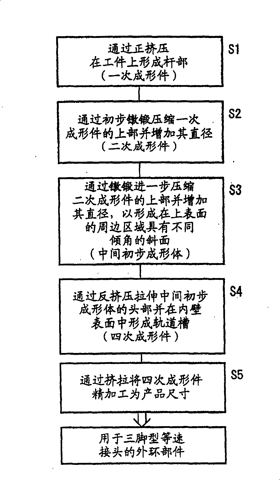
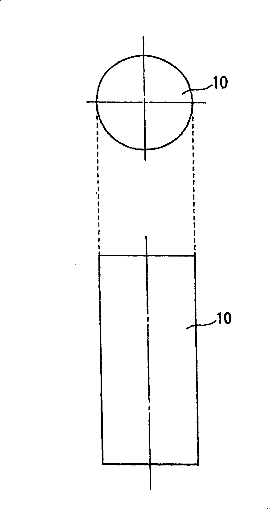
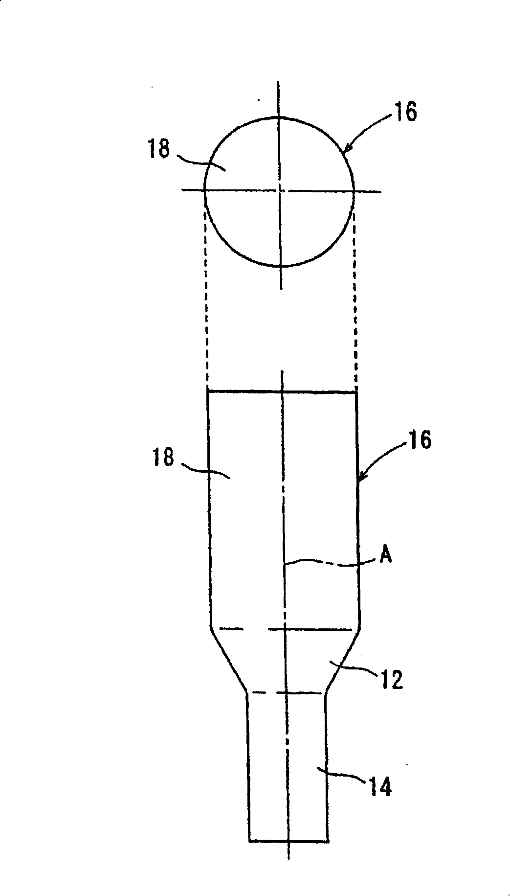
[0031] exist figure 1 The manufacturing process of the outer ring component for the constant velocity joint according to the embodiment of the present invention is shown in . Such as figure 1 As shown in the flow chart of , the workpiece 10 in the form of a carbon steel cylinder is cold-forged five times in total to finally manufacture an outer ring component for a tripod type constant velocity joint.

[0032] exist Figure 2 to Figure 7 The manner in which the shape of the workpiece 10 is changed by the manufacturing process is shown in .

[0033] In a first preparatory step, the workpiece 10 cut into the form of a cylinder having a predetermined length is treated by spheroidizing annealing (see figure 2 ). The workpiece 10 is softened so as to be easy to handle in the first to fifth cold forging steps described below.

[0034] In a second preparatory step, the workpiece 10 is coated with a lubricating chemical film. Specifically, a lubricating chemical film of zinc ph...


PUM


Abstract

A method of manufacturing an outer ring member for a constant velocity joint, comprising the steps of forming a secondary molding (20) by applying a preliminary upsetting to a work (10) after applying a forward extrusion-molding (S1) to the work (10) (S2), forming intermediate pre-molded bodies (24, 24a) having annular sloped surfaces (36, 36a) formed thereon to have a difference in flow resistance between large diameter parts (28a to 28c) and small diameter parts (30a to 30c) by applying the upsetting to the upper part (22) of the secondary molding (20) (S3, S3a), forming a quaternary molding (58) having a cup part (62) with track grooves (60a to 60c) by applying a backward extrusion-molding to the intermediate pre-molded bodies (24, 24a)(S4), and applying an ironing to the cup part (62) of the quaternary molding (58) to finish the quaternary molding (58) to product dimensions (S5).

Description

technical field [0001] The present invention relates to a method of manufacturing an outer ring part of a constant velocity joint for transmitting rotational driving force. Background technique [0002] Hitherto, it has been customary to fill the cavity formed by the upper and lower dies engaged with each other with the forging material, and to apply a pressing force to the forging material by the punch, thereby producing, for example, an outer ring of a constant velocity joint for driving a car wheel Parts (outer cup). [0003] The outer ring member includes a tubular cup and a shank integrally formed with the cup. The cup defines three axially extending track grooves in its inner peripheral surface, and the rollers can roll in and along the track grooves. [0004] For the manufacturing method of the above-mentioned type of outer ring component for constant velocity joints, for example, Japanese Patent Application Laid-Open No. 57-206537 discloses a technical idea to solv...

Claims


Application Information

Patent Timeline
Patent Type & Authority Patents(China)
IPC IPC(8): B21K1/14B21J5/06B21J5/08F16D3/20F16D3/205
Inventor 土井善久山之井薰
Owner HONDA MOTOR CO LTD
Why Eureka
Try Eureka