

Phased focusing device
A focusing device and phase control technology, applied in medical science, heating surgical instruments, ultrasonic therapy, etc.
- Summary
- Abstract
- Description
- Claims
- Application Information
AI Technical Summary
Problems solved by technology
Method used
Image

Examples
Embodiment Construction
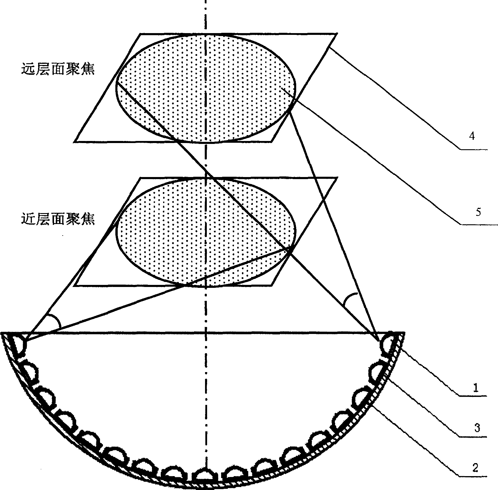
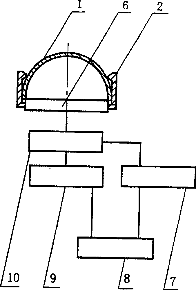
[0013] figure 1 As shown, the phase control focusing device of the present invention includes: a transmitter 3, and the transmitter 3 includes: at least 10 vibration elements, and the number of vibration elements depends on the superposition value of the focused acoustic power to meet practical applications. Such as figure 2 As shown, each vibration element includes: base 2, piezoelectric ceramic sheet 1, frequency source 6, power device 10, power supply 8, phase shifter 7 and frequency divider 9, piezoelectric ceramic sheet 1 and frequency source 6 are fixed On the base 2, the base 2 is fixed on the transmitter 3, the power supply 8 is connected to the input terminals of the phase shifter 7 and the frequency divider 9 respectively, and the output terminals of the phase shifter 7 and the frequency divider 9 are respectively connected to the power converter The input end of 10 is connected, and the output end of power device 10 is connected with frequency source 6. The piezoe...
PUM
 Abstract
Description
Claims
Application Information