

Heating spiral rod for processing plastic machine and its manufacturing method
A heating screw and plastic machine technology, applied in the field of heating screw and its production, can solve the problems of immature structure, waste of heat energy, damage to high-temperature wires of porcelain rods, etc., and achieve the advantages of convenient installation and replacement, reduced production costs, and reduced maintenance costs Effect
- Summary
- Abstract
- Description
- Claims
- Application Information
AI Technical Summary
Problems solved by technology
Method used
Image

Examples
Embodiment 2
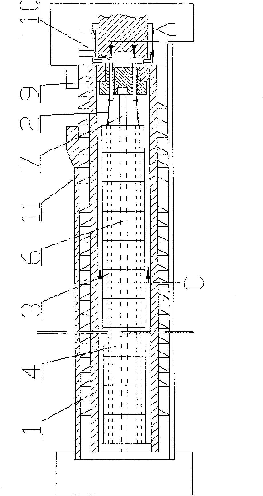
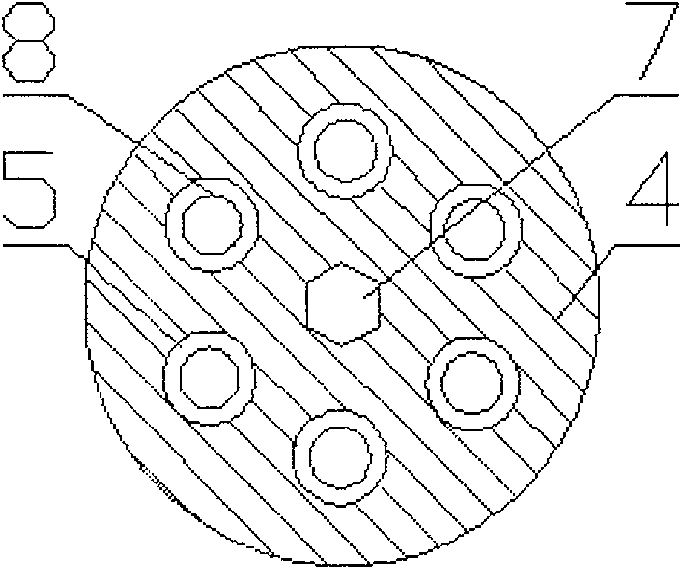
[0018] Embodiment 2 of the present invention: make hollow screw rod 1, machine pipe 11 is installed outside screw rod 1, put into 20 sections of porous refractory bricks 4 in screw rod 1, each porous refractory bricks 4 are connected in a row, on porous refractory bricks 4 A heating hole 5 is provided, and the heating hole 5 penetrates to form the long hole 3 . Make a positioning hole 6 in the middle of the porous refractory brick 4, penetrate the positioning shaft 7 in the positioning hole 6, put a plurality of porous refractory bricks 4 on the positioning shaft 7, and then the porous refractory brick 4 can be fixed. The cross sections of the positioning hole 6 and the positioning shaft 7 are regular hexagons.
[0019] Make 6 centrally symmetrical heating holes 5 on the porous refractory brick 4 . Porous refractory brick 4 is made into cylindrical shape, and length is 6 centimetres.
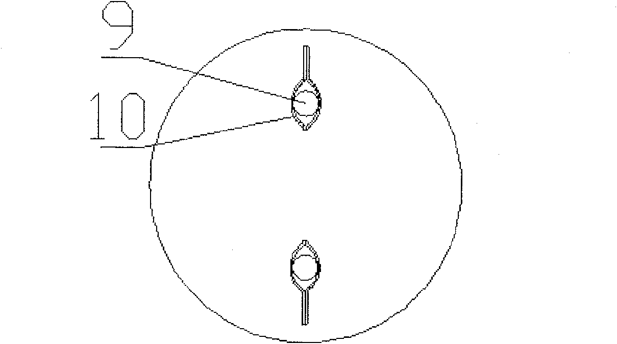
[0020] The heating element 2 adopts an electric furnace wire 8, and the connecting head of...
PUM
| Property | Measurement | Unit |
|---|---|---|
| length | aaaaa | aaaaa |
Abstract
Description
Claims
Application Information