Draw-in and draw-off unit of golf bag stand

A golf club bag and retractable device technology, which is applied in the direction of golf club bags, golf balls, sports accessories, etc., can solve the problems of easy inclusion of branches and weeds, poor movement flexibility, and affect the appearance, etc., to achieve a beautiful appearance Elegant, reduce the overall weight, improve the effect of stability

Inactive Publication Date: 2010-05-26
萧昆林
View PDF9 Cites 0 Cited by
  • Summary
  • Abstract
  • Description
  • Claims
  • Application Information

AI Technical Summary

Problems solved by technology

[0002] The known golf club bag can provide the user with two use states of upright or inclined, and the inclined placement of the golf club bag needs a pair of supporting legs to realize, figure 1 The structure of the golf club bag with linkage rod positioning shown is: when the golf club bag tripod is placed obliquely, the bag body is inclined to one side along the rotation axis of the support plate 3, and the linkage rod 1 is driven to support the tripod. 2 is stretched out in an oblique position, while the other side of the base 4 is lifted upwards. The disadvantages are: because there are more than three poles in the bag body to support the bag body and the head frame, the weight is heavy, the structure is complicated, and the movement flexibility is poor. The pole 1 is exposed, and it is easy to be mixed with branches and weeds during use, which affects the appearance; figure 2 It is the structure of the golf club bag with pull wire positioning in the background technology of the present invention: the bottom cover made of two parts is composed of a lower bottom cover 9 and an upper bottom cover 8, and the upper and lower bottom covers 8 and 9 are hinged to form a whole , when placed obliquely, the lower bottom cover 9 does not move, and the upper bottom cover 8 is lifted to the left around the hinge axis of the two, and the line body 7 passing through the bottom covers 8, 9 and fixed on the lower bottom cover 9 is on the lower bottom cover 9. A distance is pulled out from the upper base 8, and this distance is just enough to drive the support tripod 6 to open through the wrench 5. The disadvantage is that the bottom cover is made in separate parts, resulting in a complicated structure of the golf club bag and high production costs. high, a waste of raw materials, it seems cumbersome, and the appearance is not beautiful. In addition, in the process of placing the golf club bag obliquely, due to the pulling effect of the wire body 7 on the lower bottom cover 9, the lower bottom cover 9 is easy to be pulled. One end is pulled up, thereby causing two points on the end of the foot support 6 and a point on one side of the lower end cover 9 to form a supporting plane, so that the stability of the entire bag body is reduced
[0003] In addition, in the above two structures, there is a phenomenon that the foot support 6 rebounds during the process of stretching the foot support 6, that is, when the foot support 6 is stretched to the maximum position, the reaction force of the limit device will Under the action, the foot support 6 rebounds and shrinks slightly, and the foot support 6 cannot be stretched to the maximum position

Method used


Image

  • Draw-in and draw-off unit of golf bag stand
  • Draw-in and draw-off unit of golf bag stand
  • Draw-in and draw-off unit of golf bag stand

Examples


Embodiment 1

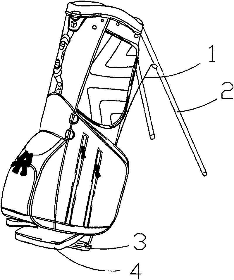
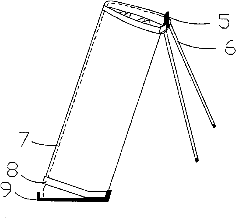
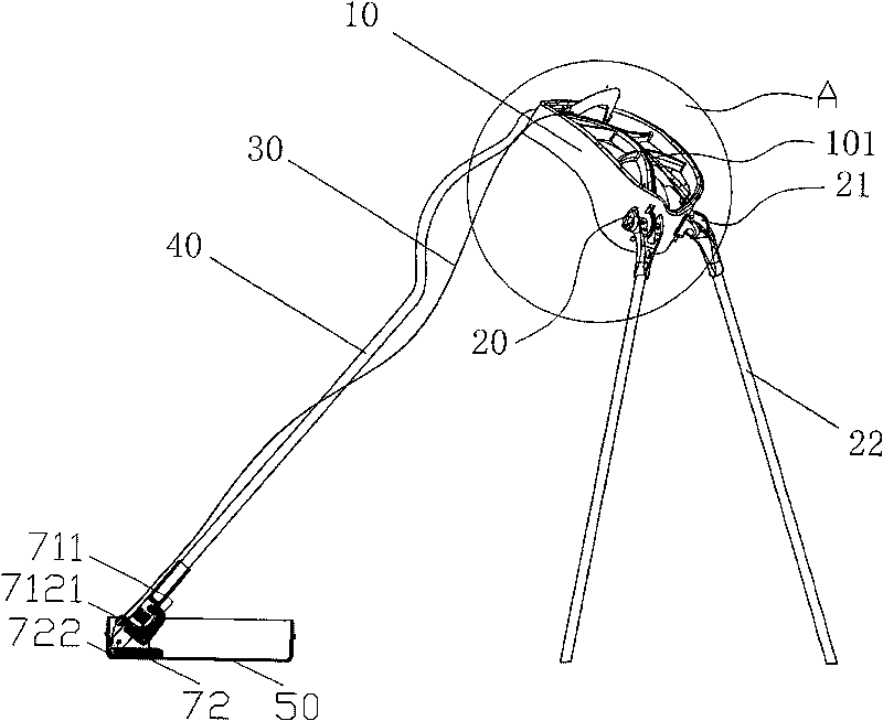
[0033] Embodiment 1: see Figure 3-11 : the foot support retractable device of the golf club bag, which is mainly composed of a wire body 30, a head frame 10, a base 50, a pole 40 and a foot support 22, and is characterized in that the upper end of the pole 40 is connected to the head frame 10, and the pole The lower end of 40 is connected on the rotating pole mounting seat 70 in the base 50, and the upper end of the wire body 30 is divided into two paths in the sash 101 of the head frame 10, and passes through the wire body guide wheels arranged on the upper end of the foot bracket 22 respectively. The groove 211 on the 21 is positioned on the two legs of the foot support 22 top, and the lower end of the wire body 40 is positioned on the golf club bag base 50.

[0034] The structure and connection relationship of the above-mentioned rotating pole mounting seat 70 is: a mounting seat 721 is arranged on the outer edge of the bottom in the base 50, and on the mounting seat 721, ...

Embodiment 2

[0040] Example 2: see Figure 4-6 , Figure 12-13 :

[0041] The foot support retractable device of the golf club bag is mainly composed of a wire body 30, a head frame 10, a base 50, a pole 40 and a foot support 22. It is characterized in that the upper end of the pole 40 is connected to the head frame 10, and the pole 40 The lower end of the wire body 30 is connected to the swingable swing plate 60 in the base 50 through the fixed pole mounting seat 62, and the upper end of the line body 30 is divided into two paths in the sash 101 of the head frame 10, and passes through the foot bracket 22 respectively. The groove 211 on the wire body guide wheel 21 of the upper end is positioned on the two legs of the foot support 22 top, and the lower end of the wire body 40 is positioned on the golf club bag base 50 .

[0042] The structure of the above-mentioned fixed pole mounting seat and its connection relationship are as follows: a swing plate 60 is arranged in the base 50, and one...


PUM


Abstract

The present invention relates to sports article technology, and is especially draw-in and draw-off unit of golf bag stand. The draw-in and draw-off unit consists of string, head frame, seat, support rod and foot support connected together. The present invention has beautiful appearance, high bag stability, flexible folding and unfolding and other advantages.

Description

Technical field: [0001] The invention relates to the technical field of sporting goods, in particular to a foot stand retractable device with beautiful appearance, linked tripod and golf club bag. Background technique: [0002] The known golf club bag can provide the user with two use states of upright or inclined, and the inclined placement of the golf club bag needs a pair of supporting legs to realize, figure 1 The structure of the golf club bag with linkage rod positioning shown is: when the golf club bag tripod is placed obliquely, the bag body is inclined to one side along the rotation axis of the support plate 3, and the linkage rod 1 is driven to support the tripod. 2 is stretched out in an oblique position, while the other side of the base 4 is lifted upwards. The disadvantages are: because there are more than three poles in the bag body to support the bag body and the head frame, the weight is heavy, the structure is complicated, and the movement flexibility is poo...

Claims


Application Information

Patent Timeline
Patent Type & Authority Patents(China)
IPC IPC(8): A63B55/06A63B55/57
Inventor 萧昆林
Owner 萧昆林
Why Eureka
Try Eureka