Lumber drying kiln

A technology for drying kilns and wood, applied in drying, drying machines, drying solid materials, etc., can solve problems such as affecting market competitiveness, inability to circulate hot air, and low thermal efficiency.

Inactive Publication Date: 2008-03-19
李祥文
View PDF0 Cites 41 Cited by
  • Summary
  • Abstract
  • Description
  • Claims
  • Application Information

AI Technical Summary

Problems solved by technology

The hot air in this kind of kiln cannot be circulated, and the thermal efficiency

Method used


Image

  • Lumber drying kiln
  • Lumber drying kiln

Examples


Example Embodiment

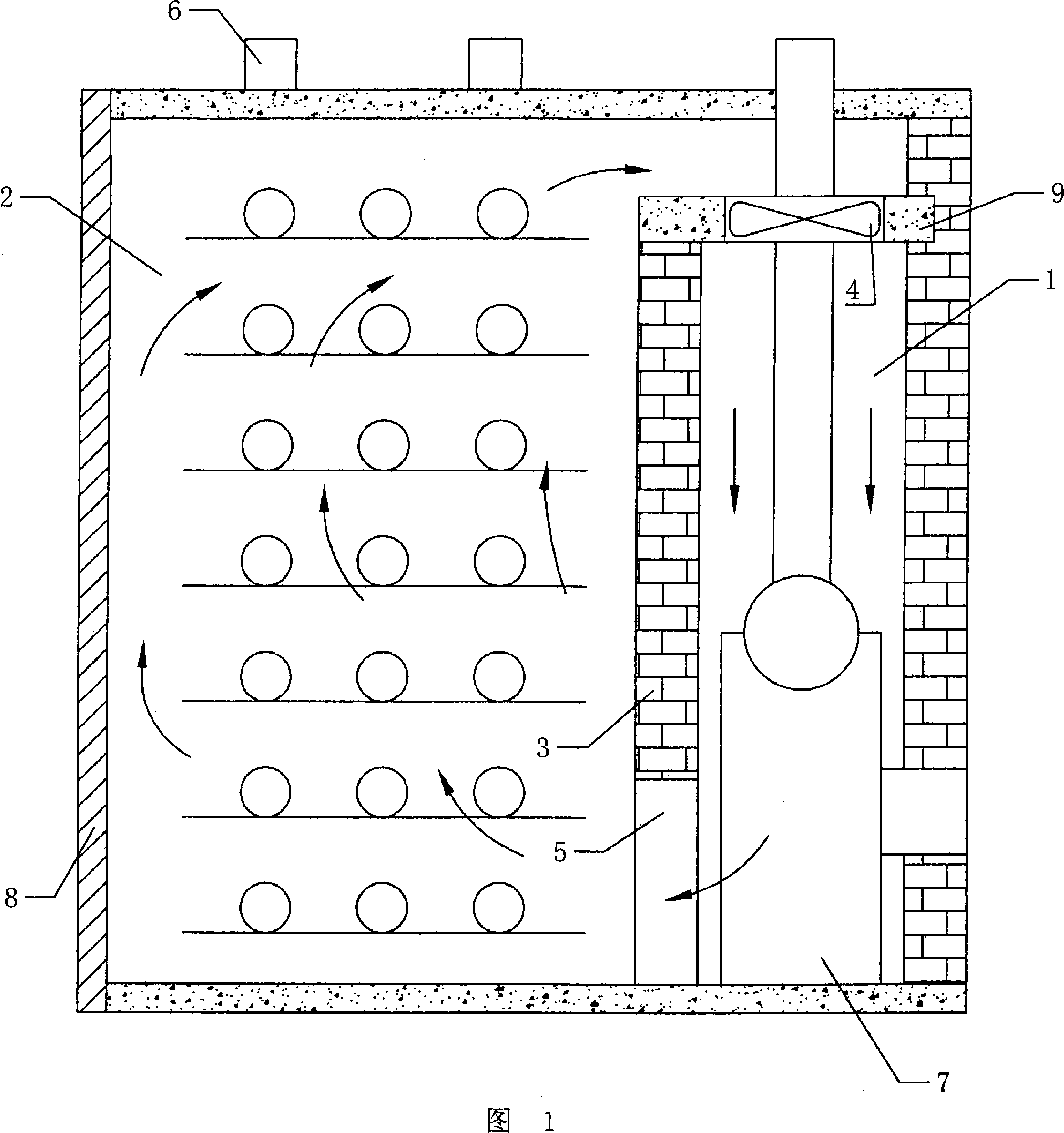
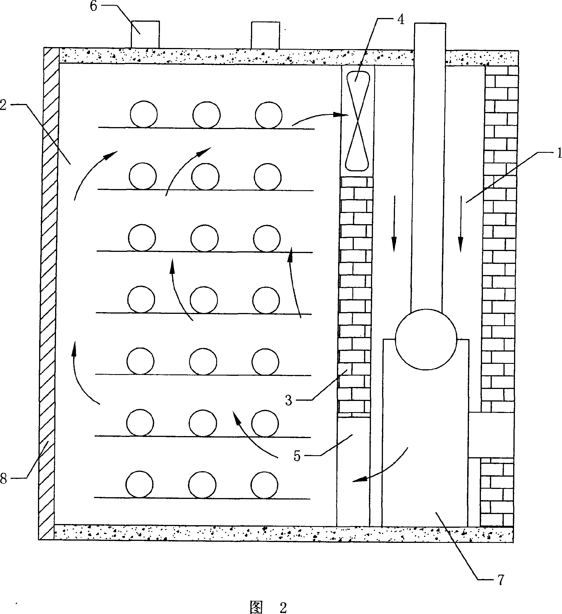
[0013] As shown in Figure 1 and Figure 2, the wood drying kiln has a partition wall extending from the ground to the kiln wall in the drying kiln. The partition wall divides the kiln space into air heating for installing the drying furnace Room 1 and wood drying room 2; the upper part of the partition wall is provided with an upper vent, the lower part of the partition wall is provided with a lower vent 5, and the upper vent is provided with a space for going from the wood drying chamber 2 to The air heating chamber 1 blows a fan 4; the top kiln wall of the wood drying chamber 2 is provided with an exhaust channel 6.

[0014] The isolation wall includes a vertical wall 3 extending upward from the ground, a horizontal partition 9 arranged between the top of the vertical wall 3 and the side kiln wall of the air heating chamber 1, and the upper vent 9 is opened in the The horizontal partition 9 mentioned above.

[0015] The isolation wall is composed of a vertical wall 3 extending up...


PUM


Abstract

The invention discloses a lumber drying kiln. An isolation wall is arranged between the bottom part and the top part in the drying kiln, the isolation wall divides the space in the kiln into an air heating room used for installing a drying furnace, and a lumber drying room; wherein, an upper ventilation opening is arranged at the upper part of the isolation wall, a lower ventilation opening is arranged at the lower part of the isolation wall, a fan used for blowing air to the air heating room from the lumber drying room is arranged between the air heating room and the lumber drying room; an air exhaust passage is arranged at the top part corresponding to the lumber drying room; because the fan is arranged at the position of the upper ventilation opening, the fan sucks the hot air from the lumber drying room to blow into a lumber heating room, the back flow does not happen, thereby leading the heated air circulation to be smoother, therefore the drying quality to be improved. Because the isolation wall is arranged between the air heating room and the lumber drying room, the charring of the lumber close to a combustion furnace because of over high temperature is avoided, the lumber far away the combustion furnace does not have the drying phenomenon, to lead the drying to be evener.

Description

technical field [0001] The invention relates to the technical field of a drying kiln, in particular to a wood drying kiln specially used for drying wood. Background technique [0002] At present, a known wood drying kiln has an independent drying chamber and a heating chamber, wood is placed in the drying chamber, a hot air passage is provided between the drying chamber and the heating chamber, and an exhaust hole is provided at the bottom of the drying chamber. . When in use, place wood in the drying room, and introduce the hot air generated in the heating room into the drying room through the hot air channel. Since the hot air rises naturally, and the cold moisture falls, the moisture is discharged from the exhaust hole, and the hot air The air dries the wood. The hot air of this kind of kiln cannot be circulated, and the thermal efficiency is low, which causes the high cost of wood drying and affects the market competitiveness. Contents of the invention [0003] The ...

Claims


Application Information

Patent Timeline
IPC IPC(8): F26B9/02F26B21/00F26B3/06
Inventor 李祥文丁占科
Owner 李祥文
Why Eureka
Try Eureka