Brightness control circuit and backlight control module

A technology of brightness control and voltage control circuit, applied in electric light source, electroluminescence light source, electric lamp circuit layout, etc., can solve the problems of increased circuit cost, different brightness, power consumption of display screen, etc., to reduce power consumption and circuit cost. Low, fast response effect

Inactive Publication Date: 2008-08-13
ASIA OPTICAL CO INC
View PDF0 Cites 4 Cited by
  • Summary
  • Abstract
  • Description
  • Claims
  • Application Information

AI Technical Summary

Problems solved by technology

[0004] However, the traditional control display device needs to additionally use a DC-to-DC converter 10 to provide a certain voltage source, and an additional constant current controller 20 to provide current, which makes the circuit more complicated and the circuit cost is also increased a lot
[0005] In addition, the photosensitive components of traditional digital cameras are all installed in the lens, but often because the brightness of the lens end is different from the brightness of the display screen (behind the lens), the brightness sensed by the photosensitive component is different from the brightness actually felt by the user, resulting in The brightness adjustment results of the display screen of traditional digital cameras are often too bright or too dark, which cannot meet the needs of users, and the display screen is too bright to cause unnecessary power consumption

Method used


Image

  • Brightness control circuit and backlight control module
  • Brightness control circuit and backlight control module
  • Brightness control circuit and backlight control module

Examples


Embodiment Construction

[0063] In order to make the above-mentioned and other objects, features and advantages of the present invention more comprehensible, the preferred embodiments are listed below, together with the accompanying drawings, and are described in detail as follows:

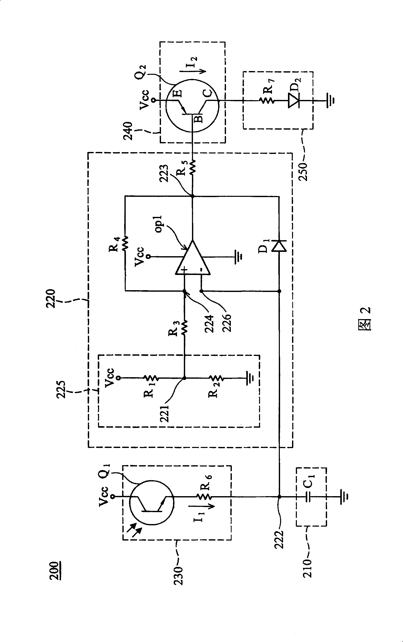
[0064] FIG. 2 is a circuit diagram of a brightness control circuit 200 according to an embodiment of the invention. The brightness control circuit 200 includes a voltage control circuit 220 , a photosensitive module 230 , a charging module 210 , a switch 240 and a light emitting module 250 . The photosensitive module 230 includes a photosensor Q1 and a resistor R6, and is connected between the charging module 210 and the voltage source Vcc. The photosensor Q1 is connected between the voltage source Vcc and the resistor R6, and generates a first current I flowing through the photosensitive module 230 according to the intensity of the received light. 1 , when the light is strong, a larger current is provided, and when the ...


PUM


Abstract

The invention relates to a luminance control circuit, which is suitable for controlling luminance of light module. Reference voltage source is used for providing reference voltage level. Light sensitive module is used for generating first current passing through light sensitive module based on lighting strength. Charging module is connected between light sensitive module and ground, and generates charging level according to first current upon electric voltage node. Voltage control circuit includes comparator and diode, wherein the comparator comprises positive input terminal connected to reference voltage source, negative input terminal connected to voltage node, and first output terminal, outputs corresponding comparative signal according to relation between reference electric level and charging level, and the diode is connected between negative input terminal and first output terminal. The switch is connected to voltage control circuit, and provides second current passing through luminous module according to comparative signal.

Description

technical field [0001] The present invention relates to a brightness control circuit, in particular to a brightness control circuit using pulse width modulation technology. Background technique [0002] Currently, electronic products on the market use display screens to display information, such as mobile phones, digital cameras, personal digital assistants (Personal Digital Assistant, PDA), satellite navigation (Global Positioning System, GPS) and so on. When the ambient brightness is bright, the display screen needs to be displayed at a high brightness, so that users can easily see the content displayed on the screen in a bright environment. In addition, in a dark environment, the display The screen is displayed with a lower brightness to save power, and when the user watches the display screen, he will not feel uncomfortable due to the excessive brightness difference between the display screen and the environment. Most of the above-mentioned electronic products use batte...

Claims


Application Information

Patent Timeline
Patent Type & Authority Applications(China)
IPC IPC(8): H05B37/02H05B33/08G05F1/46H05B44/00
Inventor 宋勇俊
Owner ASIA OPTICAL CO INC
Why Eureka
Try Eureka