Dual frequency band ultrasound transducer arrays

一种超声换能器、换能器的技术,应用在仪器、声波的再辐射、测量装置等方向

Inactive Publication Date: 2008-09-10
比约恩・A・J・安杰尔森
View PDF6 Cites 17 Cited by
  • Summary
  • Abstract
  • Description
  • Claims
  • Application Information

AI Technical Summary

Problems solved by technology

This wide band poses particular challenges to the vibrational design of the structure of the array due to the need for most of the HF and LF radiating surfaces to be common

Method used


Image

  • Dual frequency band ultrasound transducer arrays
  • Dual frequency band ultrasound transducer arrays
  • Dual frequency band ultrasound transducer arrays

Examples


Embodiment Construction

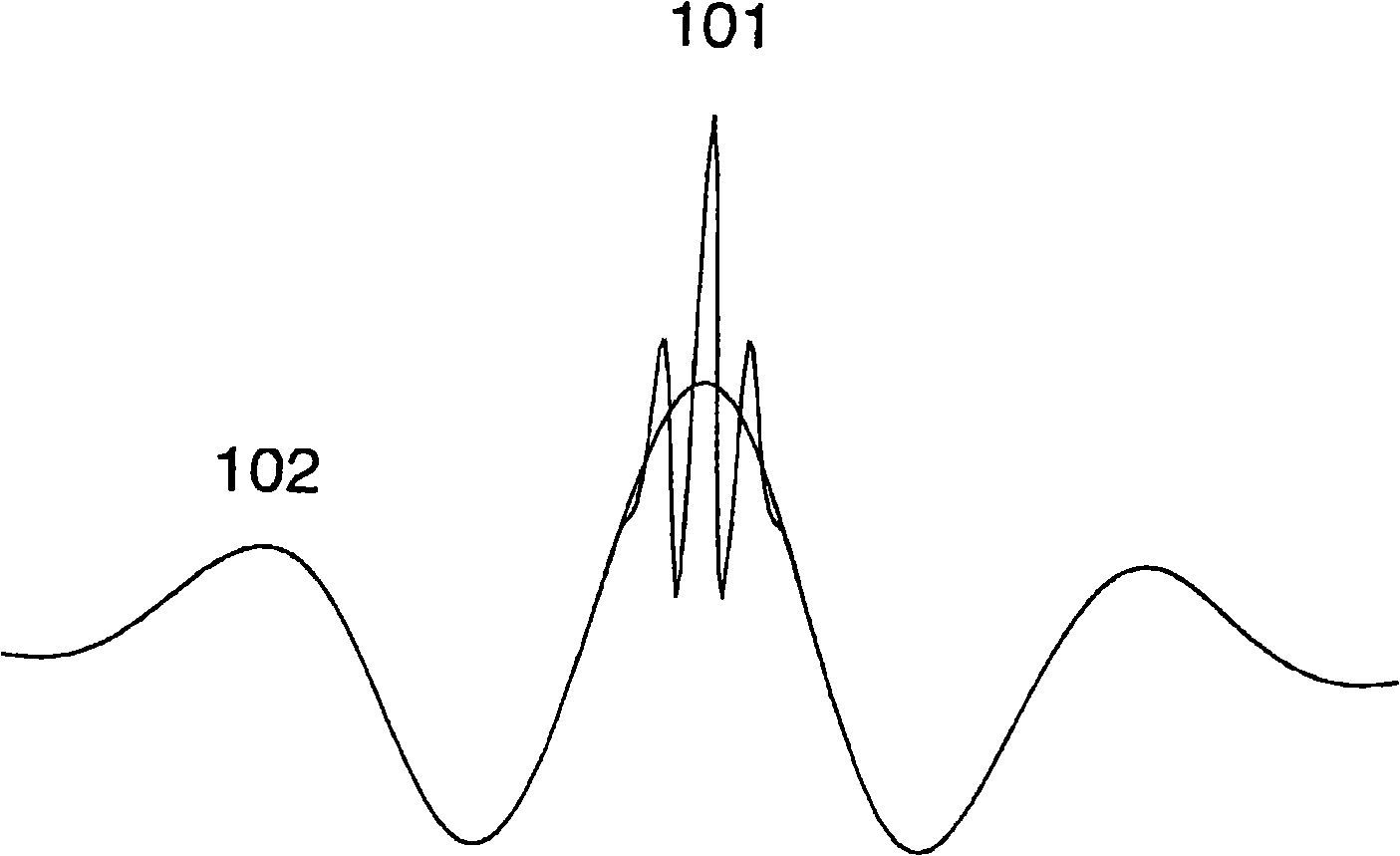
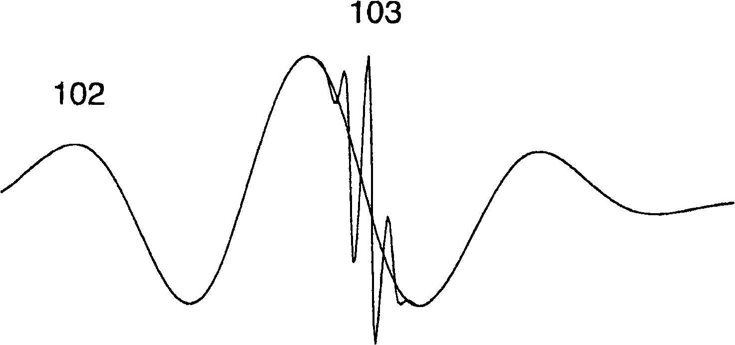
[0027] Exemplary embodiments of the present invention will now be described with reference to the accompanying drawings. A general example of a dual frequency pulse that is intended to be transmitted is shown in Figure 1 as described above. The challenge in array design is the design of the radiating surface such that the HF pulse remains in the desired position for the LF pulse for the imaging range, while maintaining sufficient amplitude of the LF pulse, while the vibration The design of the structure allows the emission of LF and HF pulses with such a wide separation between frequencies from the same surface.

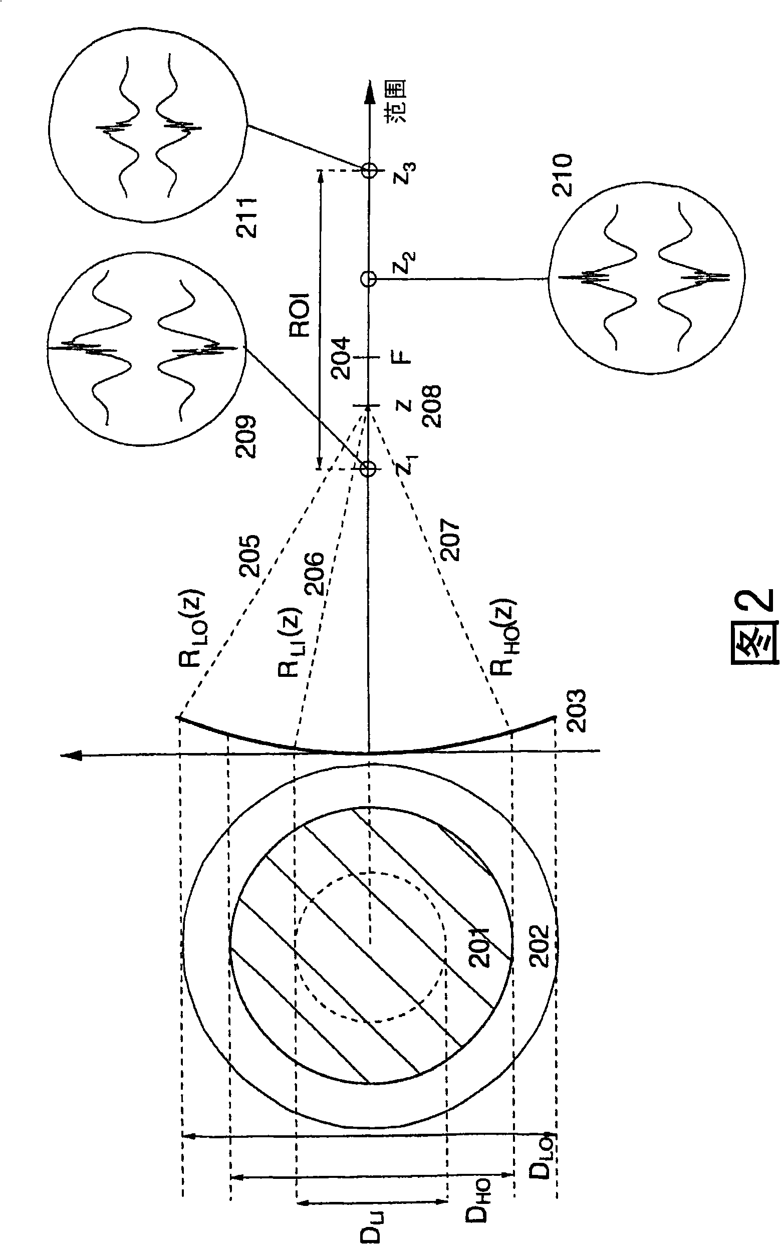
[0028] In some applications it is important that the amplitude of the LF pulse at the position of the HF pulse is as high as possible and nearly constant over the entire imaging range. This requires a large aperture of the LF radiating surface to avoid diffractive propagation of the LF beam due to the long wavelength of the LF pulse compared to the HF pulse. The wi...


PUM


Abstract

Ultrasound probes that transmits / receives ultrasound pulses with frequencies both in a low frequency (LF) and a high frequency (HF) band, where the radiation surfaces of said HF and LF bands at least have a common region. Several solutions for transmission (and reception) of LF and HF pulses through the same radiation surface are given. The arrays and elements can be of a general type, for example linear phased or switched arrays, or annular arrays or elements with division in both azimuth and elevation direction, like a 1.5D, a 1.75D and a full 2D array. The LF and HF element division and array apertures can also be different.

Description

technical field [0001] The present invention relates to techniques and designs for efficient acoustic (acoustic and ultrasonic) body wave transducers operating in at least two frequency bands simultaneously. Applications of the transducer are for example but not limited to: medical ultrasound imaging, non-destructive testing, industrial and biological inspection, geological applications and SONAR applications. Background technique [0002] Exploiting the nonlinear elasticity of tissue and ultrasound contrast agent microbubbles in medical ultrasound imaging provides improved images with less noise. A wider application is in the field of so-called harmonic imaging, where the second harmonic component of the transmitted frequency band is used for imaging. The use of third and fourth harmonic components for imaging is also proposed in US Patent 6,461,303. [0003] In Br Heart J. 1984 Jan;51(1):61-9 dual band transmit pulses are used for M-mode and Doppler measurements. Furthe...

Claims


Application Information

Patent Timeline
Patent Type & Authority Applications(China)
IPC IPC(8): B06B1/06
CPCB06B1/064G01S15/8952G01S15/8915G01S7/52022
Inventor 比约恩·A·J·安杰尔森T·F·约翰森R·汉森S-E·马索伊P·内斯霍尔姆
Owner 比约恩・A・J・安杰尔森
Why Eureka
Try Eureka