Electric tank working control device

A work control and electrolytic cell technology, applied in the field of electrolytic cell work control devices, can solve the problems of easy omission or misremembering, troublesome production conditions, inconvenient production management, etc., and achieve the effects of simple structure, easy operation and low cost

Active Publication Date: 2010-08-04
GUIZHOU BRANCH CHINA ALUMINUM IND
View PDF1 Cites 0 Cited by
  • Summary
  • Abstract
  • Description
  • Claims
  • Application Information

AI Technical Summary

Problems solved by technology

[0002] At present, most of the production status of the electrolytic cell is obtained by on-site observation, manual recording, and then monitoring of the cell with problems. The on-site personnel cannot timely understand the working status of the cell. After judging that there is a problem with the cell, they often have to go to the site to record. , due to the large number of electrolyzers, it is not only cumbersome to manually record the production status, but also prone to omissions or misremembering. Manually moving the anode when "preheating" the tank will cause danger and bring inconvenience to production management

Method used


Image

  • Electric tank working control device
  • Electric tank working control device

Examples


Embodiment

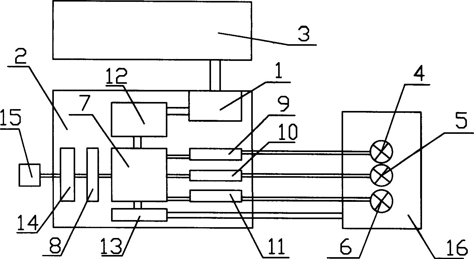
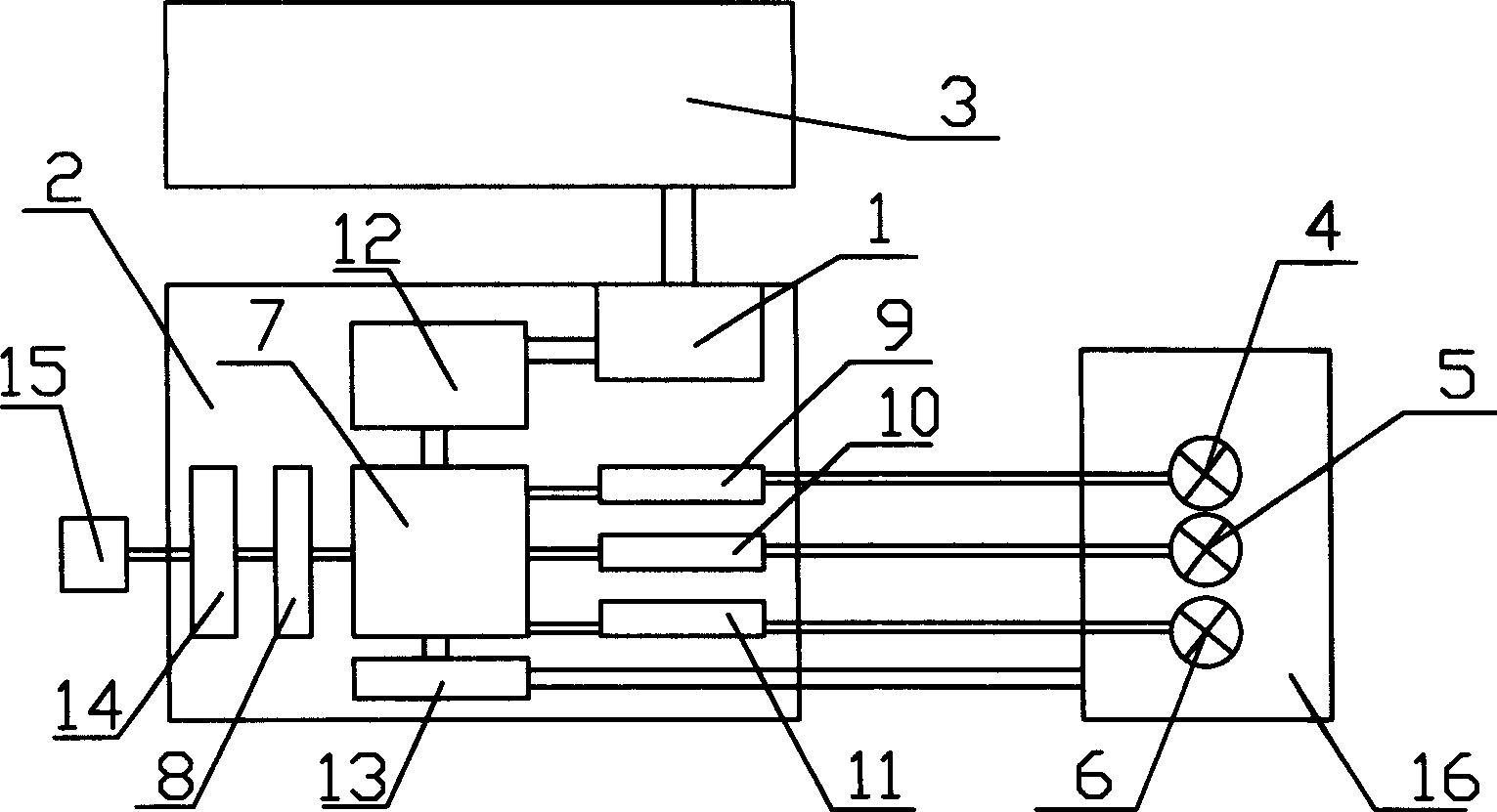
[0012] Embodiment: the slot control machine 2 is connected with the interface machine 3; it is characterized in that: the slot control machine 2 is provided with a communication interface 1, the interface machine 3 is connected with the communication interface 1, and the CPU control chip 7 is connected to the communication interface through the first isolation circuit 12 1 connection, the CPU control chip 7 is connected to the first driver chip 9, the first driver chip 9 is connected to the preheating indicator light 4, the CPU control chip 7 is connected to the second driver chip 10, the second driver chip 10 is connected to the damaged indicator light 5 Connect, CPU control chip 7 is connected with the 3rd drive chip 11, and the 3rd drive chip 11 is connected with normal indicator light 6; 16 is connected to the CPU control chip 7 through multiple signals through the fourth drive chip 13; the CPU control chip 7 is connected to the 12V relay 14 through the second isolation cir...


PUM


Abstract

The invention discloses an operation control device for an electrolyte tank. A tank control machine (2) is provided with a communication interface (1) inside, an interface message processor (3) is connected with the communication interface (1), a CPU controller chip (7) is connected with the communication interface (1) through a buffer circuit (12), the CPU controller chip (7) is connected with apreheating indicator light (4), a broken indicator light (5), and a normal indicator light (6). In order to facilitate field observation, the invention adds an arrangement of a 'broken tank' state, and adds the indicator lights displaying 'preheating', 'broken' and 'normal', so that a field administrator can intuitively know the current working condition of the electrolyte tank, moving the anode is avoided in 'preheating' the tank, the operation security is ensured, and meanwhile the electrolyte tank displaying 'broken' is paid with more attention to reduce the possibility of the sink condition. The structure is simple, the operation is easy, and the cost is low.

Description

technical field [0001] The invention relates to an electrolytic cell production device, in particular to an electrolytic cell operation control device. Background technique [0002] At present, most of the production status of the electrolytic cell is obtained by on-site observation, manual recording, and then monitoring of the cell with problems. The on-site personnel cannot timely understand the working status of the cell. After judging that there is a problem with the cell, they often have to go to the site to record. , due to the large number of electrolyzers, it is not only cumbersome to manually record the production status, but also prone to omissions or misremembering. Artificially moving the anode when "preheating" the tank will cause danger and bring inconvenience to production management. Contents of the invention [0003] The object of the present invention is to provide a working control device for an electrolytic cell. The device can reflect the condition of...

Claims


Application Information

Patent Timeline
Patent Type & Authority Patents(China)
IPC IPC(8): C25C3/20
Inventor 龚春雷朱宏斌刘彬杨孟刚张培青崔健
Owner GUIZHOU BRANCH CHINA ALUMINUM IND
Why Eureka
Try Eureka