IGBT driving and wave-pushing and current-limiting circuit control method

A technology of wave-by-wave current limiting and circuit control, applied in emergency protection circuit devices, electrical components, etc., can solve problems such as damage to the main power tube, damage to switching devices, etc., to achieve the effect of improving system stability

Active Publication Date: 2019-07-19
商宇(深圳)科技有限公司
View PDF7 Cites 0 Cited by
  • Summary
  • Abstract
  • Description
  • Claims
  • Application Information

AI Technical Summary

Problems solved by technology

The switching device of the inverter is easily damaged by the impact of instantaneous high current, so a protection circuit is needed to protect the switching device of the inverter
[0003] The above existing technical solutions have the following defects: the inverter on the UPS power supply has multiple IGBT transistors. causing damage

Method used


Image

  • IGBT driving and wave-pushing and current-limiting circuit control method
  • IGBT driving and wave-pushing and current-limiting circuit control method
  • IGBT driving and wave-pushing and current-limiting circuit control method

Examples


Embodiment 1

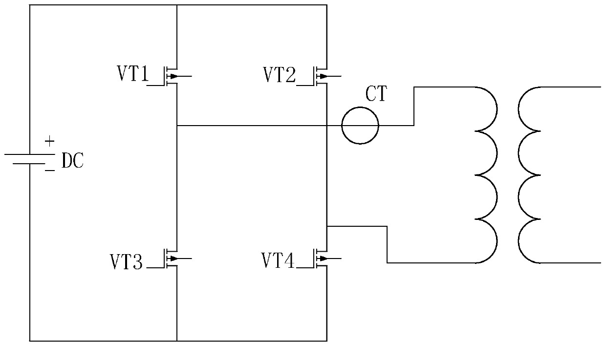
[0055] Embodiment 1: An IGBT driving and wave-by-wave current limiting circuit control method, such as figure 1 with figure 2 As shown, the specific steps are as follows:

[0056] S1. The current transformer is connected with the IGBT transistor, the current transformer detects the current value of the transformer when the IGBT transistor is turned on, and transmits the collected current value to the wave-by-wave current limiting circuit.

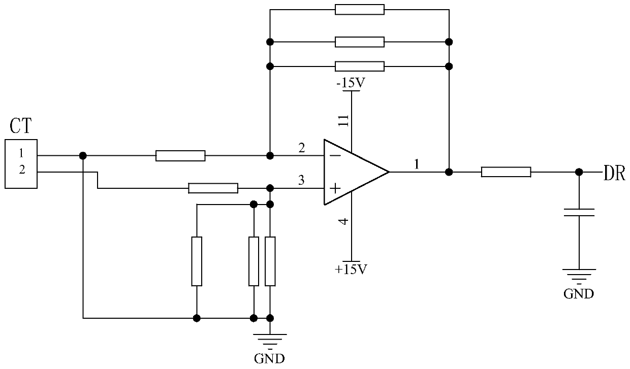
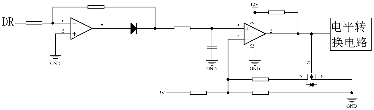
[0057] S2, combine image 3 , The wave-by-wave current-limiting circuit will collect the current value through the amplifying circuit and put it out in a small amplitude ratio. The wave-by-wave current-limiting circuit forms a steamed bun wave after a small amplitude proportional current value is rectified by a diode half bridge. The wave-by-wave current-limiting circuit inputs the steamed bread wave into the comparison circuit. When the peak value of the steamed-bread wave exceeds the reference voltage of the reverse input terminal of the com...

Embodiment 2

[0062] The second embodiment is an IGBT driving and a wave-by-wave current limiting circuit control method. The difference between this embodiment and the first embodiment is that it further includes the following steps:

[0063] S6. The memory of the microprocessor receives the steamed bread wave generated by the wave-by-wave current limiting circuit in real time, and the memory stores the peak value of the steamed bread wave.

[0064] S7. The microprocessor periodically calls the peak value of the steamed bread wave stored in the microprocessor, and the microprocessor selects the peak value of the steamed bread wave as the y-axis and the time as the x-axis to make a waveform diagram. The microprocessor sends the waveform diagram back to the memory for storage, and at the same time deletes the peak value of the steamed bun wave corresponding to the waveform diagram stored in the memory.

[0065] S8. After receiving the self-checking instruction, the microprocessor calls the waveform...


PUM


Abstract

The invention discloses an IGBT driving and wave-pushing and current-limiting circuit control method, and belongs to the fields of a UPS power band inductive load and a rectifying load; the method comprises the steps of S1, acquiring the current value of a transformer during conduction of an IGBT transistor in real time, and transmitting the acquired current value to a wave-pushing and current-limiting circuit; S2, making comparison between the acquired current value and a set current limiting threshold value by the wave-pushing and current limiting circuit, and when the current value exceedsthe set current limiting threshold value, enabling the wave-pushing and current-limiting circuit to generate a wave-pushing and current-limiting enabling signal; S3, transmitting the wave-pushing andcurrent-limiting enabling signal to a microprocessor through a level conversion circuit, wherein the microprocessor turns off the IGBT transistor; S4, if the current of the transformer is reduced, andthe current value is lower than the set current limiting threshold value, enabling the IGBT transistor to be conducted again; and S5, repeating the steps S2 to S4 until the current value of the transformer is lower than the set current limiting threshold value when the IGBT transistor is conducted. By virtue of the method, each current peak value exceeding the limit value of a main power tube canbe accurately limited.

Description

Technical field [0001] The invention relates to the technical field of UPS power supply with inductive load and rectifying load, in particular to an IGBT drive and a wave-by-wave current limiting circuit control method. Background technique [0002] At present, UPS power supply is a system equipment that connects batteries (mostly lead-acid maintenance-free batteries) with the host, and converts DC power into mains power through module circuits such as the host inverter. An inverter is a device that converts DC power (battery, storage battery) into AC power (usually 220V, 50Hz sine wave). The switching devices of the inverter are susceptible to damage caused by instantaneous high current impact. For this reason, a protection circuit is needed to protect the switching devices of the inverter. [0003] The above-mentioned existing technical solutions have the following defects: the inverter on the UPS power supply has multiple IGBT transistors. When the current passed by the IGBT tr...

Claims


Application Information

Patent Timeline
Patent Type & Authority Applications(China)
IPC IPC(8): H02H7/122
CPCH02H7/122H02H7/1227
Inventor 赖吉民李毅黄新发
Owner 商宇(深圳)科技有限公司
Why Eureka
Try Eureka