Solar battery and manufacturing method thereof

a solar battery and manufacturing method technology, applied in the field of solar batteries, can solve the problems of disadvantage in appearance, deterioration of solar battery properties, and deterioration of properties and/or problems in appearance, and achieve the effect of reducing manufacturing costs and excellent yield

Inactive Publication Date: 2005-04-14
SHARP KK
View PDF6 Cites 44 Cited by
  • Summary
  • Abstract
  • Description
  • Claims
  • Application Information

AI Technical Summary

Benefits of technology

[0031] The present invention is made to solve the problems described above, and its object is to provide a manufacturing method of a solar battery that enables excellent yield and reduced manufacturing costs

Problems solved by technology

These leaks invite deterioration of the properties of the solar battery.
Accordingly, if a solar battery is produced following the similar steps as a non-crystalline silicon, a film peels off in the cleaning s

Method used


Image

  • Solar battery and manufacturing method thereof
  • Solar battery and manufacturing method thereof
  • Solar battery and manufacturing method thereof

Examples


example 1

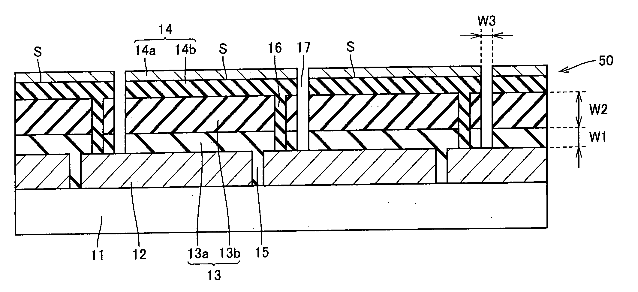
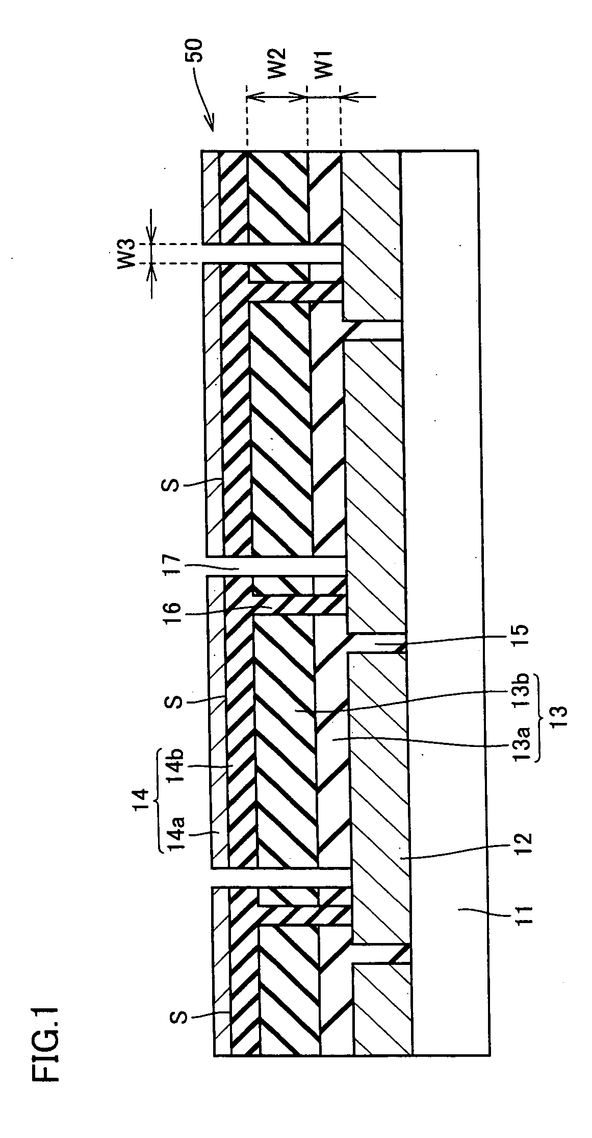
[0102] Using a glass substrate having a thickness of about 4.0 mm as insulation translucent substrate 11, on the glass substrate (substrate size 560 mm×925 mm), SnO2 (tin oxide) was deposited by thermal CVD method as transparent conductive film 12.

[0103] Next, using fundamental harmonic of YAG laser, patterning of transparent conductive film 12 was performed. By setting the light to enter from the glass surface, transparent conductive film 12 was separated into rectangular pieces and surface electrode separation line 15 was formed.

[0104] Thereafter, the substrate was subjected to an ultrasonic cleaning by pure water, and thereafter upper cell 13a was formed. Upper cell 13a was formed of a-Si:Hp layer, a-Si:Hi layer, and a-Si:Hn layer, and the total thickness W1 was set to be about 0.25 μm. It should be noted that p-layer and n-layer may be μc-Si:H.

[0105] Next, lower cell 13b was formed. Lower cell 13b was formed of μc-Si:Hp layer, μc-Si:Hi layer, and μc-Si:Hn layer, and the total...

example 2

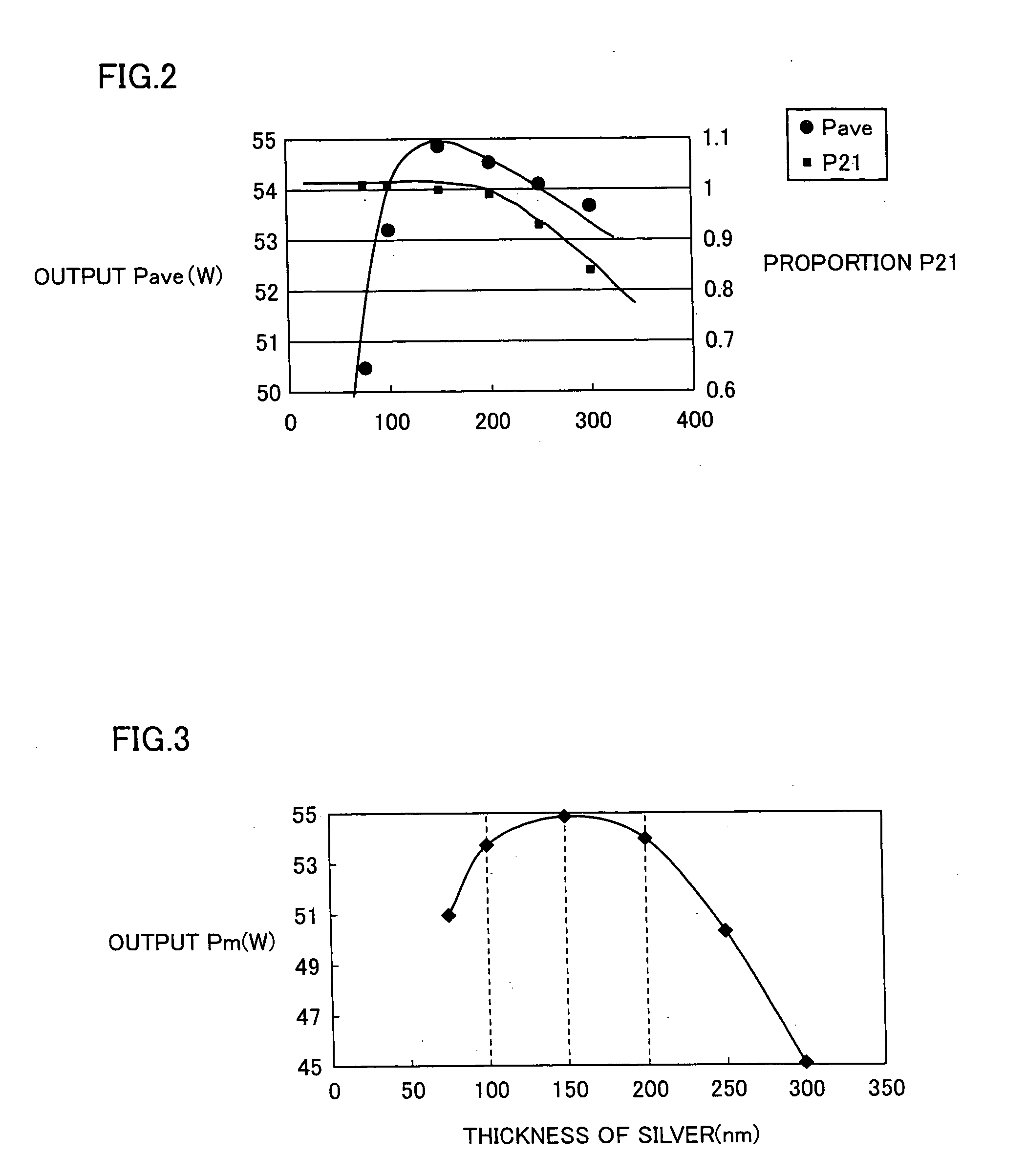
[0111] Processes were performed similarly to Example 1 except that the thickness of silver (back surface metal electrode) was set to be 100 nm. Similarly to Example 1, the back surface electrode separation line was observed by a microscope, and almost no burr was found. FIG. 2 shows average output Pave (W) and proportion P21=(second average output / first average output) of a solar battery thus produced. FIG. 3 shows average output Pm (W) after formed in a module (i.e., Pm=Pave×P21).

example 3

[0112] Processes were performed similarly to Example 1 except that the thickness of silver (back surface metal electrode) was set to be 200 nm. Similarly to Example 1, the back surface electrode separation line was observed by a microscope, and almost no burr was found. FIG. 2 shows average output Pave (W) and proportion P21=(second average output / first average output) of a solar battery thus produced. FIG. 3 shows average output Pm (W) after formed in a module (i.e., Pm=Pave×P21).


PUM


Abstract

A solar battery and a manufacturing method thereof, which includes a plurality of power generation regions having at least an insulation translucent substrate, a front surface electrode, a photoelectric conversion layer made of semiconductor films being stacked, and a back surface electrode, the front surface electrode and the back surface electrode of adjacent power generation regions being electrically connected, whereby the power generation regions are serially connected. The solar battery and the manufacturing method thereof are characterized in that the back surface electrode has a back surface metal electrode having a thickness of 100 nm-200 nm.

Description

[0001] This nonprovisional application is based on Japanese Patent Application No. 2003-3511929 filed with the Japan Patent Office on Oct. 10, 2003, the entire contents of which are hereby incorporated by reference. BACKGROUND OF THE INVENTION [0002] 1. Field of the Invention [0003] The present invention relates to a solar battery and a manufacturing method thereof. [0004] 2. Description of the Background Art [0005] Recently, the technical development of a solar power generation system that directly generates electric energy from sunlight using a solar battery has been advancing rapidly, and its technical prospect is favorable as a power generating method for practical use. As a result, expectation for the future of the solar power generation system has been increasing, as a full-scale clean energy technique that protects the global environment of the 21 st century from the environmental pollution caused by combustion of fossil energy. [0006] Here, materials used for solar batteries...

Claims


Application Information

Patent Timeline
IPC IPC(8): H01L25/00H01L31/0224H01L31/04H01L31/042H01L31/0468H01L31/06H01L31/076H02N6/00
CPCH01L31/046Y02E10/50H01L31/0463Y02E10/548
Inventor TACHIBANA, SHINSUKESANNOMIYA, HITOSHITANAMURA, HIROMASAOUCHIDA, TAKASHI
Owner SHARP KK
Why Eureka
Try Eureka