Microstructured optical fibre with cladding recess, a method of its production, and apparatus comprising same

a microstructured optical fibre and cladding recess technology, applied in the direction of cladding optical fibre, optical elements, instruments, etc., can solve the problems of ineffective coupling of pump light, limited output power, and difficulty in accessing signals, etc., to achieve high degree of high confinement of light, and mechanical robustness of fibres

Inactive Publication Date: 2005-06-02
CRYSTAL FIBRE AS
View PDF10 Cites 43 Cited by
  • Summary
  • Abstract
  • Description
  • Claims
  • Application Information

AI Technical Summary

Benefits of technology

[0039] In a preferred embodiment, the outer cladding features are arranged in a first outer cladding region, whereby the first outer cladding can provide a high confinement of light in the inner cladding—typically in terms of having a high NA.
[0040] In a preferred embodiment, the outer cladding further comprises a second

Problems solved by technology

Despite the very high intensity in the embedded single mode core, in excess of 100 MW/cm2, no damage to the fibre was observed, and the output power was only limited by the amount of light that could be launched into the fibre.
Moreover, access to the signal is rendered difficult by the end-pumping scheme.
This is particularly problematic in an optical amplifier configuration.
However, prior art

Method used


Image

  • Microstructured optical fibre with cladding recess, a method of its production, and apparatus comprising same
  • Microstructured optical fibre with cladding recess, a method of its production, and apparatus comprising same
  • Microstructured optical fibre with cladding recess, a method of its production, and apparatus comprising same

Examples


Embodiment Construction

“Microstructures Optical Fibre”

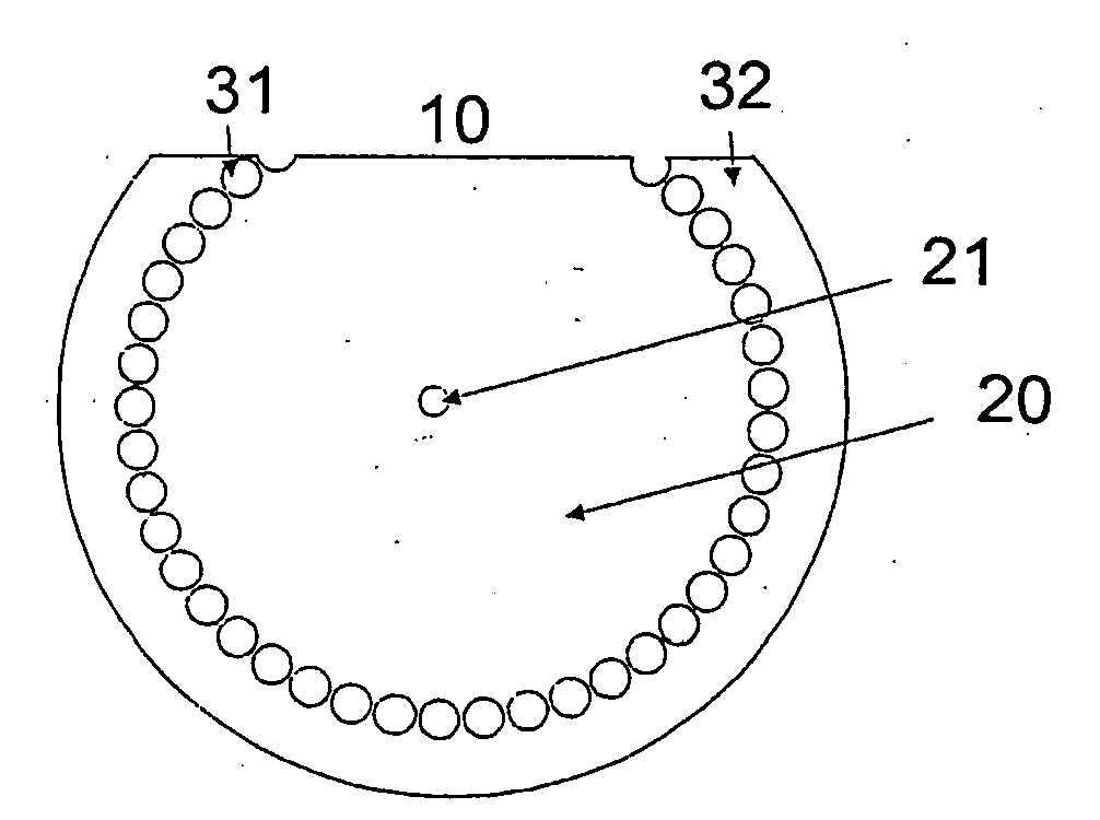
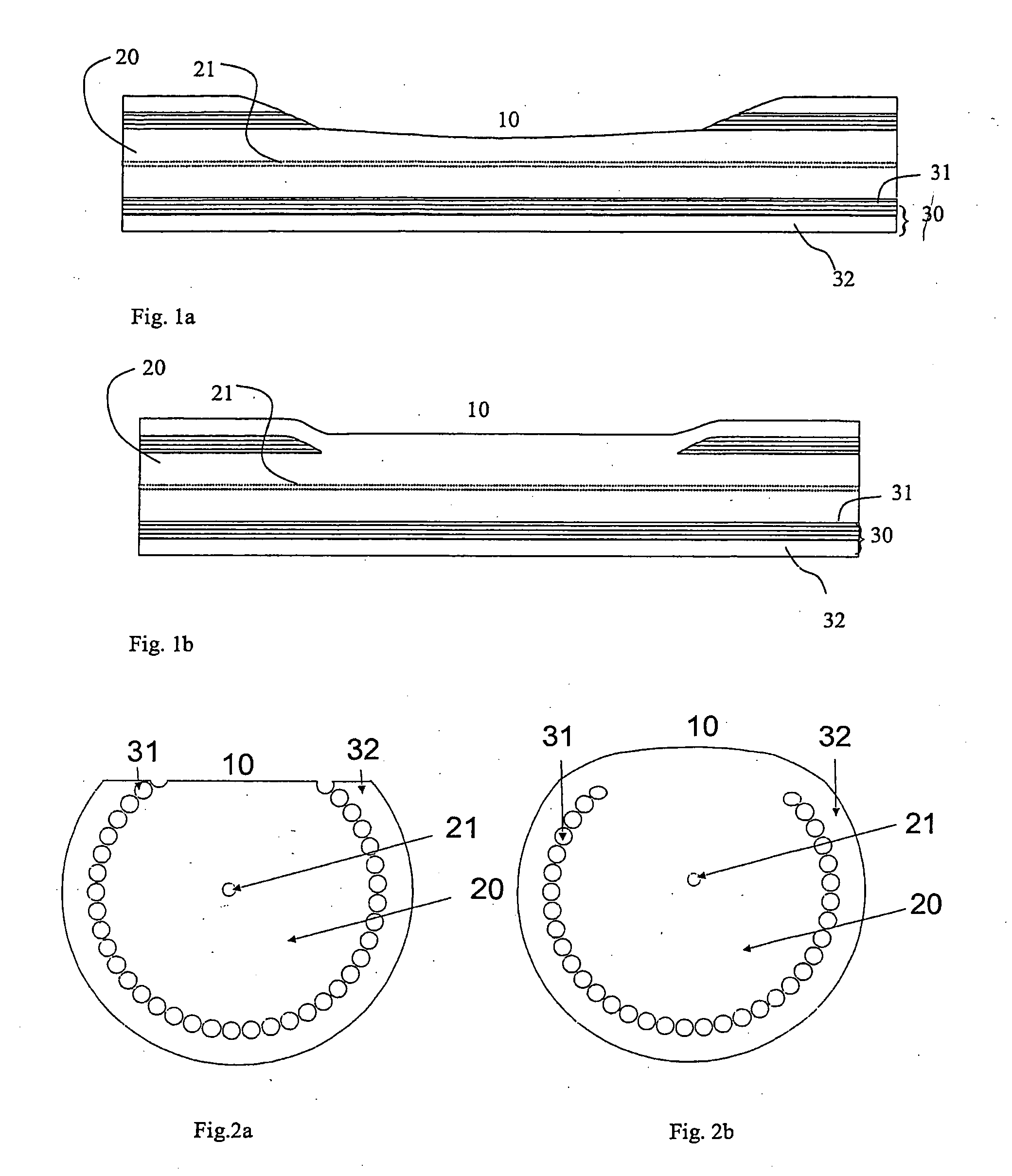
[0136]FIG. 1 shows a schematic, longitudinal view of an example of a preferred embodiment of a microstructured fibre according to the present invention, the microstructured fibre comprising a cladding recess. FIG. 2 shows a schematic, cross-sectional view of the microstructured fibre shown in FIG. 1.

[0137] The microstructured fibre comprises an inner cladding 20, and an outer cladding 30 around the inner cladding. The outer cladding comprises a first outer cladding region 31 having elongated features extending along the fibre axis. The outer cladding region optionally comprises a further second outer cladding region 32, e.g. in a solid form. The elongated features in the outer cladding allow guiding in the inner cladding 20 either by modified total internal reflection or by the photonic band gap effect. A coating, usually made of a polymer, surrounds the outer cladding to protect the fibre mechanically. This coating is typically stripped in the vicini...


PUM


Abstract

A microstructured optical fibre comprising an inner cladding and an outer cladding; said outer cladding comprising elongated outer cladding features extending in an axial direction of the fibre, and at least one cladding recess extending at least partly through the outer cladding in a radial direction to the inner cladding; said cladding recess providing optical access to the inner cladding; a method of forming a cladding recess in such an optical fibre comprising a step of collapsing a part of the outer cladding features by use of a heat source; an apparatus comprising such a microstructured optical fibre, preferably a laser or an amplifier.

Description

BACKGROUND OF THE INVENTION [0001] The present invention relates to a microstructured optical fibre with cladding recess, preferably a microstructured optical fibre exhibiting a high numerical aperture; a method of its production; and an apparatus comprising a length of such a microstructured fibre, preferably a side-pumped optical fibre laser or optical fibre amplifier. [0002] 1. The Technical Field [0003] Today optical fibres are mainly used in point to point communication were the power transmitted remains modest, rarely exceeding 100 mW. But with the deployment of metropolitan networks large saturation power amplification is sought, to allow for large signal splitting ratios at nodes. The advent of high power is also expected to open new markets to fibre lasers such as marking, thermal printing, inter-satellite communication, and material processing. [0004] In recent years the power delivered by laser diodes in form of single stripes, bars, or arrays has increased rapidly. [0005...

Claims


Application Information

Patent Timeline
IPC IPC(8): G02B6/02G02B6/28G02B6/34G02B6/42H01S3/067H01S3/094
CPCG02B6/02338G02B6/02347G02B6/02357G02B6/02361G02B6/02366H01S3/094019G02B6/2852G02B6/34G02B6/4206H01S3/06708H01S3/094003G02B6/02376
Inventor VIENNE, GUILLAUMEJAKOBSEN, CHRISTIANBROENG, JESFOLKENBERG, JACOB RIISSKOVGAARD, PETER M.W.
Owner CRYSTAL FIBRE AS
Why Eureka
Try Eureka