Hydraulic valve

a technology of hydraulic valves and valves, applied in the direction of valve details, valve arrangement, valve operating means/releasing devices, etc., can solve problems such as degrading control quality, and achieve the effects of reducing the volume of piston plungers, reducing the exchange volume, and increasing overall robustness

Active Publication Date: 2018-10-23
HILITE GERMANY
View PDF9 Cites 0 Cited by
  • Summary
  • Abstract
  • Description
  • Claims
  • Application Information

AI Technical Summary

Benefits of technology

[0013]In order to assure the function of hydraulic valves in mechatronic transmission controls it is necessary as a matter of principle to provide the bearings of magnets as robust as possible against an impact of external influences. Thus, in addition to obtaining mechanical robustness a robustness against contaminated operating media is of essential importance. In particular large particles can lead to an impairment of the magnet function and the valve function and thus to an impairment of the magnet function and / or the hydraulic function up to a failure through blocking due to the small operating clearances and running clearances. A direct connection of the magnetic and hydraulic portions, this means of the magnet portion and the hydraulic portion of the hydraulic valve facilitates an exchange of the contaminated medium.
[0015]Through the spatial separation of magnet portion and the hydraulic portion of the hydraulic valve an exchange of contaminant particles between the magnet portion and the hydraulic portion of the hydraulic valve, wherein the contaminant particles impair the magnet function and / or the hydraulic function, can be significantly reduced. In particular a negative influence upon the armature movement in the pole tube and a magnet / valve—hysteresis thus induced can be prevented.
[0016]Furthermore the seal element helps to significantly reduce an exchange volume between the magnet portion and the hydraulic portion of the hydraulic valve through a reduction of the piston plunger volume that is arranged in the magnet portion.
[0017]Thus simple and cost effective remedies increase overall robustness and service life of the hydraulic valve due to a reduced contaminant introduction into the magnet portion. Thus, the magnetic transversal forces in the portion of the piston plunger and thus the valve hysteresis can be significantly reduced.
[0018]Advantageously the seal element is provided pressed into an end section of the valve bushing, wherein the end section is at least partially received by the actuator. Thus, the impressing process is a cost effective and simple method to establish a seal between the valve portion and the magnet portion of the hydraulic valve.
[0019]According to an advantageous embodiment of the invention the seal element is configured as a disc that is U-shaped in a cross sectional view and which includes an inner arm and an outer arm and which can be advantageously configured as a cost effective deep drawn component. Advantageously the piston plunger penetrates the inner arm of the seal element without contacting it so that a seal between the seal element and the piston plunger is configured as a gap seal. Thus, an exchange of the hydraulic fluid can be reduced to a minimum in a simple manner through a ratio of seal length to seal height of the seal gap.

Problems solved by technology

This high level of robustness can be achieved with large clearances for moving parts which, however, degrades control quality.

Method used


Image

  • Hydraulic valve
  • Hydraulic valve
  • Hydraulic valve

Examples


Embodiment Construction

[0026]In the drawing figures identical or equivalent components are designated with identical reference numerals. The figures merely illustrate advantageous embodiments and do not limit the scope and spirit of the invention.

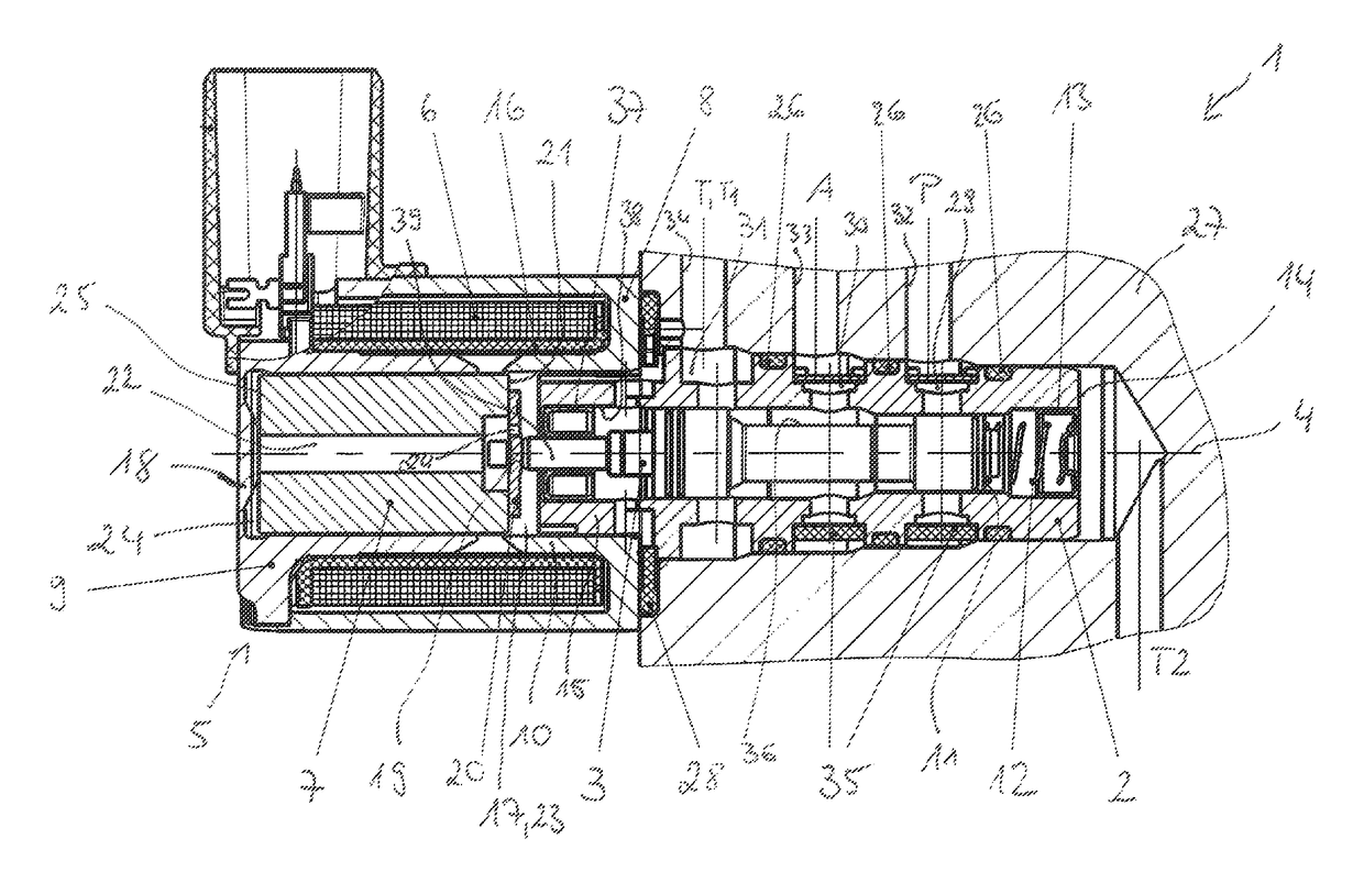
[0027]FIG. 1 illustrates a longitudinal sectional view of a hydraulic valve 1 according to an embodiment of the invention. The hydraulic valve 1 is configured as a proportional valve and is used for example in an automatic transmission.

[0028]The hydraulic valve includes a valve bushing 2 and a valve piston 3 that is axially moveable in a bore hole 35 of the valve busing 2 along a longitudinal axis 4 of the valve bushing 2 wherein the bore hole includes shoulders. The valve piston 3 is movable by an electromagnetic actuator of the hydraulic valve 1. The actuator 5 which represents the magnet potion of the hydraulic valve 1 includes an armature 7 that is operatively connected with the valve piston 3, wherein the armature is coaxially arranged relative to the valve ...


PUM


Abstract

A hydraulic valve including a valve bushing; a valve piston that is axially moveable in the valve bushing along a longitudinal axis of the valve bushing; a supply connection configured to feed a hydraulic fluid; at least one operating connection; and at least one tank drain configured to drain the hydraulic fluid, wherein the valve piston is movable by an electromagnetic actuator of the hydraulic valve and the valve bushing forms a hydraulic portion and the actuator forms a magnetic portion of the hydraulic valve, characterized in that a seal element is arranged in the valve bushing which seal element provides a spatial separation of the magnet portion and the hydraulic portion, and wherein the seal element is penetrated by an end of the valve piston configured as a piston plunger.

Description

RELATED APPLICATIONS[0001]This application claims priority from and incorporates by reference German Patent Applications[0002]DE 10 2015 113 331.8 filed on Aug. 13, 2015,[0003]DE 10 2016 104 310.9 filed on Mar. 9, 2016, and[0004]DE 10 2016 108 067.5 filed on May 2, 2016.FIELD OF THE INVENTION[0005]The invention relates to a hydraulic valve with a hydraulic portion and a magnet portion, in particular for a mechatronic transmission control of a motor vehicle.BACKGROUND OF THE INVENTION[0006]In order to still be failsafe after long transmission oil change intervals, in the extreme for so called service lift fillings the transmission valve has to have a high level of robustness. This high level of robustness can be achieved with large clearances for moving parts which, however, degrades control quality.[0007]A hydraulic valve is known from DE 10 2011 053 023 A1 which has a high level of robustness in addition to a high level of control quality. The high level of robustness is achieved i...

Claims


Application Information

Patent Timeline
Patent Type & Authority Patents(United States)
IPC IPC(8): F16K31/06
CPCF16K31/0613F15B13/02F16K31/0675F16K11/0708F16K27/041F16H61/0009F16K11/07F16K27/048F16K31/061
Inventor BOBAN, DRAZENJACOB, THOMASKNECHT, ANDREASSENST, OLIVERVIERTLER, DANIEL
Owner HILITE GERMANY
Why Eureka
Try Eureka