
Multi-layer mesoporous coatings for conductive surfaces, and methods of preparing thereof

a technology of conductive surfaces and mesoporous coatings, which is applied in the field of two-layer mesoporous coatings, can solve the problems of limited manufacturing to high-cost batch processes that compete with silicon-based solar cells, short operation life of dssc cells, and increased manufacturing costs of photovoltaic cells. , to achieve the effect of efficient charge transport and mechanical robustness

Inactive Publication Date: 2016-01-21
ONESUN
View PDF6 Cites 0 Cited by
  • Summary
  • Abstract
  • Description
  • Claims
  • Application Information

AI Technical Summary

Benefits of technology

The patent describes methods for making a photocatalytic surface that can be coated at lower temperatures than current methods. This results in a surface that is stronger and can transport electricity efficiently. This makes it suitable for use in PV cells.

Problems solved by technology

Although Grätzel cells are fabricated from relatively inexpensive raw materials, the high temperature sintering technique used to make these cells limits the substrate choices to rigid transparent materials, such as glass, and consequently limits the manufacturing to high cost batch processes that compete with Silicon based solar cells.
Furthermore, the high temperature sintering process increases the cost of manufacturing a photovoltaic cell due to the high energy requirement.
In addition, DSSC cells may experience short operational lifetime as a result of the dye disrobing from the nanotitania particles.

Method used


Image

  • Multi-layer mesoporous coatings for conductive surfaces, and methods of preparing thereof
  • Multi-layer mesoporous coatings for conductive surfaces, and methods of preparing thereof
  • Multi-layer mesoporous coatings for conductive surfaces, and methods of preparing thereof

Examples


embodiment 1

2. The method of embodiment 1, wherein the ratio of the amount of first photocatalytic particles to the amount of polymeric binder present in the first photocatalytic dispersion is 0.36 to 0.65.

embodiment 2

3. The method of embodiment 2, wherein the ratio of the amount of first photocatalytic particles to the amount of polymeric binder present in the first photocatalytic dispersion is 0.38 to 0.42.

4. The method of any one of embodiments 1 to 3, wherein at least 30% of each first photocatalytic particle in the porous first layer is coated with the polymeric binder.

5. The method of any one of embodiments 1 to 4, wherein the conductive surface is an indium tin oxide or fluorinated tin oxide surface.

6. The method of any one of embodiments 1 to 5, wherein the multi-layered mesoporous structure is a two-layered mesoporous structure.

7. The method of any one of embodiments 1 to 6, wherein the first photocatalytic particles and the photocatalytic particles are each independently semiconductive oxide particles.

embodiment 4

8. The method of embodiment 4, wherein the first photocatalytic particles and the second photocatalytic particles are each independently titanium dioxide particles, zirconium dioxide particles, zinc oxide particles, or any combination thereof.

9. The method of any one of embodiments 1 to 8, wherein the average particle size of the plurality of second photocatalytic particles is less than the average particle size of the plurality of first photocatalytic particles.

10. The method of any one of embodiments 1 to 8, wherein the plurality of first photocatalytic particles has an average particle size between 8 nm and 10 nm.

11. The method of any one of embodiments 1 to 8, wherein the plurality of first photocatalytic particles has an average particle size between 10 nm and 250 nm.


PUM

PropertyMeasurementUnit
temperatureaaaaaaaaaa
particle sizeaaaaaaaaaa

Abstract

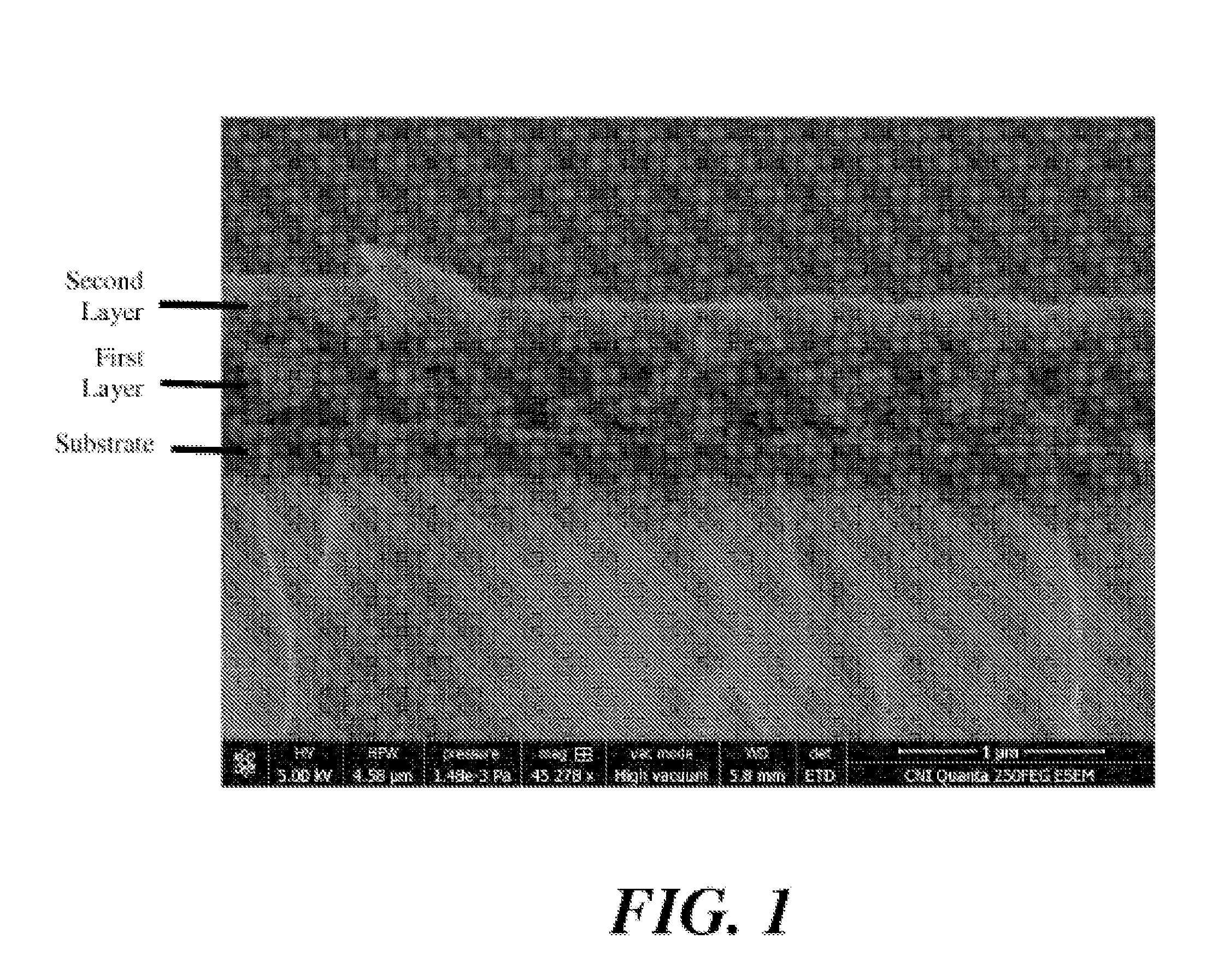
Provided herein is a method of coating a conductive surface with a multi-layer mesoporous structure, by coating a conductive surface with a first photocatalytic dispersion to form a first layer over the conductive surface, curing or partially curing the first layer at temperatures of less than 400° C. to form a porous structure, and coating the porous first layer with the one or more additional photocatalytic dispersions to form one or more additional layers that can penetrate or partially penetrate the pores of the structure in the first layer. The first photocatalytic dispersion includes photocatalytic particles, polymeric binder and a dispersion medium. The one or more additional photocatalytic dispersions include photocatalytic particles and a dispersion medium.

Description

CROSS-REFERENCE TO RELATED APPLICATION[0001]This application claims the benefit of U.S. Provisional Patent Application No. 61 / 835,354, filed on Jun. 14, 2013, the disclosure of which is hereby incorporated by reference in its entirety.FIELD[0002]The present disclosure relates generally to photovoltaic devices, and more specifically to a two-layer mesoporous structure, and methods of preparing such structures, that can be used in photovoltaic cells and modules.BACKGROUND[0003]Thin film photovoltaic (PV) cells made up of percolating networks of liquid electrolyte and dye-coated sintered titanium dioxide were developed by Dr. Michael Grätzel and coworkers at the Swiss Federal Institute of Technology, in the early eighties. See Int. J. Electrochem. Sci., Vol. 7, 2012. These PV devices fall within a general class of cells referred to as dye-sensitized solar cells (DSSCs). Conventionally, fabrication of DSSCs requires a high temperature sintering process, typically greater than about 400°...

Claims


Application Information

Patent Timeline
Patent Type & Authority Applications(United States)
IPC IPC(8): H01G9/20
CPCH01G9/2031H01L31/02167H01L31/02327B01J37/0244B01J37/0219B01J21/063B01J23/005B01J23/14B01J27/135Y02E10/542B01J35/39B01J35/40B01J35/23B01J35/651B01J35/647Y02E10/50
Inventor BURKETT, ADAM J.LARSSON, MATS I.ZEIRA, EITAN C.
Owner ONESUN
Learn More