
Heavy-current charging cable for charging an electric vehicle

a charging cable and electric vehicle technology, applied in the direction of power cables, cables, insulated conductors, etc., can solve the problems of not having good thermal performance, being too heavy and stiff for the user, and working at the very limit of the material temperature is not recommended for reliability

Pending Publication Date: 2022-05-12
ABB E-MOBILITY BV
View PDF0 Cites 1 Cited by
  • Summary
  • Abstract
  • Description
  • Claims
  • Application Information

AI Technical Summary

Benefits of technology

This patent describes a solution for charging cables and charge posts that allows for high-power charging at power ratings up to 500kw. The solution is designed to provide better thermal performance, reliability, safety, and mechanical robustness using cost-effective cooling units.

Problems solved by technology

As a consequence they would become too heavy and stiff for the user.
On the other hand, the cooling performance is penalized due to presence of insulating, and poor thermally conducting, layers between the conductors and the cooling liquid, limiting in existing solutions known from prior art, the maximum allowed power rating of the liquid cooled charging cable.
Nevertheless, said existing solutions do not have good thermal performance when heat removed by conductors is direct released to the ambient air.
In order to stay within the temperature limit of the commonly used materials, such as for example cross-linked polyethylene, a derating of the maximum charging current is needed at ambient temperature above 30 to 35° C. Working at the very limit of the material temperature is not recommended for reliability.
Moreover, adopted materials however become brittle, thus less reliable, at low temperatures.
Finally, the selected fluids have generally very high viscosity at low temperature or are not environmentally friendly.
Currently available data on chemical compatibility between these fluids and the material is scarce and questionable.
Furthermore, in existing solutions, coolant flow can be easily blocked as an example by inner clogging or pipe crushing, which represents potentially a safety issue, especially during a charging session because a thermal runaway can be extremely fast and an interlock system in a charge post may only intervene with a certain delay.
This makes the refrigeration based cooling unit more expensive and less reliable.

Method used


Image

  • Heavy-current charging cable for charging an electric vehicle
  • Heavy-current charging cable for charging an electric vehicle

Examples


Embodiment Construction

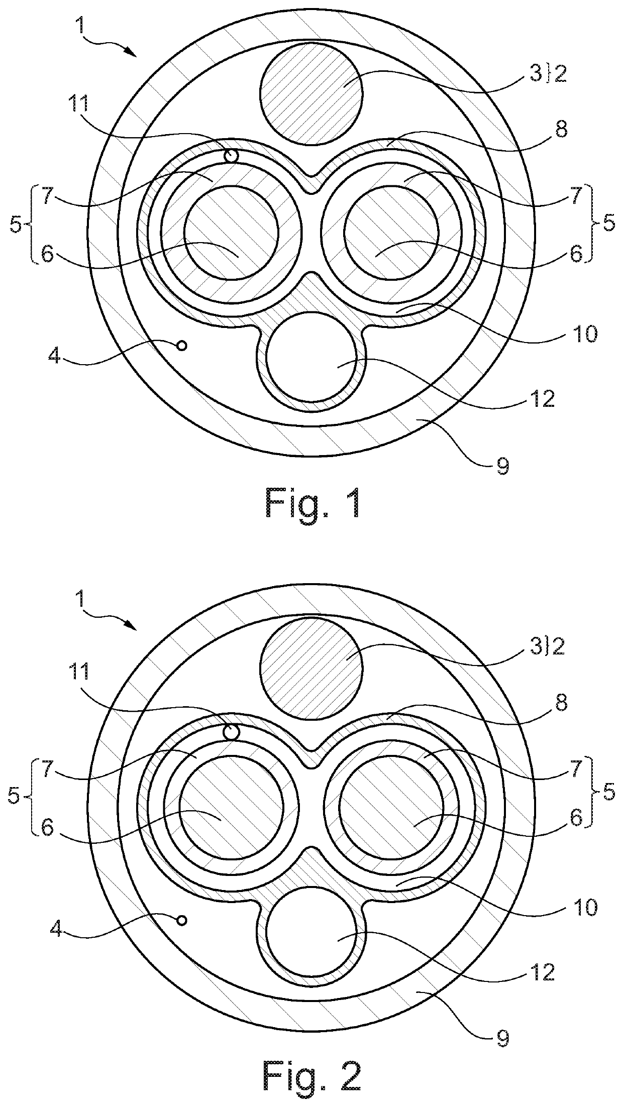
[0015]In one aspect, the present disclosure describes a charging cable and respective charge post solution for overcoming above described limitations thus allowing high power charging at power ratings equal or greater to 500 kW increasing thermal performance while providing mechanical robustness, reliability and safety with the use of simple and cost-effective cooling units.

[0016]In another aspect, the present disclosure describes a heavy-current charging cable for charging an electric vehicle, comprising: a ground heavy-current wire configured for serving as ground, the ground heavy-current wire comprising a ground conductor and extending in a longitudinal direction, at least two heavy-current power wires configured for conducting positive and negative direct current, DC, each of said heavy-current power wires comprising a power conductor and a power wire insulation surrounding said power conductor, the heavy-current power wires extending parallel to the ground wire, a liquid tight...


PUM


Abstract

A charging cable includes a ground conductor and extending in a longitudinal direction, at least two heavy-current power wires for conducting positive and negative direct current, each comprising a power conductor and insulation, the heavy-current power wires extending parallel to the ground wire, a liquid tight inner sheath extending in the longitudinal direction and surrounding the heavy-current power wires to define a first hollow area between and around the heavy-current power wires, liquid coolant being provided between the heavy-current power wires along the longitudinal direction, wherein the liquid tight inner sheath comprises a second hollow area extending in the longitudinal direction, arranged adjacent to at least one of the heavy-current power wires and comprising liquid coolant to flow within the second hollow area, and a liquid tight outer sheath extending in the longitudinal direction and surrounding the inner sheath and the ground heavy-current wire.

Description

CROSS-REFERENCE TO RELATED APPLICATIONS[0001]This patent application is a continuation of International patent application no. PCT / EP2019 / 077984, filed on Oct. 15, 2019, which claims priority to European patent application 19188409.7, filed on Jul. 25, 2019, which are incorporated herein in their entirety by reference.FIELD OF THE DISCLOSURE[0002]The present disclosure relates to a heavy-current charging cable for charging an electric vehicle.BACKGROUND OF THE INVENTION[0003]Conventional charging cables for charging electric vehicles, in particular non-cooled or air cooled charging cables, are used in applications where a charging current is below 250 A. For higher currents, conventional solutions would require a very large cross section of the charging cables. As a consequence they would become too heavy and stiff for the user.[0004]At charging currents above 250 A, an active liquid cooling system is essential for removing heat generated by Joule effect both in the charging cable a...

Claims


Application Information

Patent Timeline
IPC IPC(8): B60L53/18B60L53/16B60L53/302H01B7/42H01B9/00
CPCB60L53/18B60L53/16H01B9/006H01B7/425B60L53/302Y02T10/70Y02T10/7072Y02T90/14Y02T90/12
Inventor BORTOLATO, MATTEOLOGAKIS, EMMANUELBOEHM, MORITZOPPLIGER, JEAN-MARC
Owner ABB E-MOBILITY BV
Learn More