
Electrodes and methods for microbial fuel cells

a fuel cell and microorganism technology, applied in the field of microorganism fuel cells, can solve problems such as limit power production, and achieve the effects of increasing the maximum power density, improving performance parameters, and increasing positive surface charg

Inactive Publication Date: 2008-11-27
PENN STATE RES FOUND
View PDF28 Cites 118 Cited by
  • Summary
  • Abstract
  • Description
  • Claims
  • Application Information

AI Technical Summary

Benefits of technology

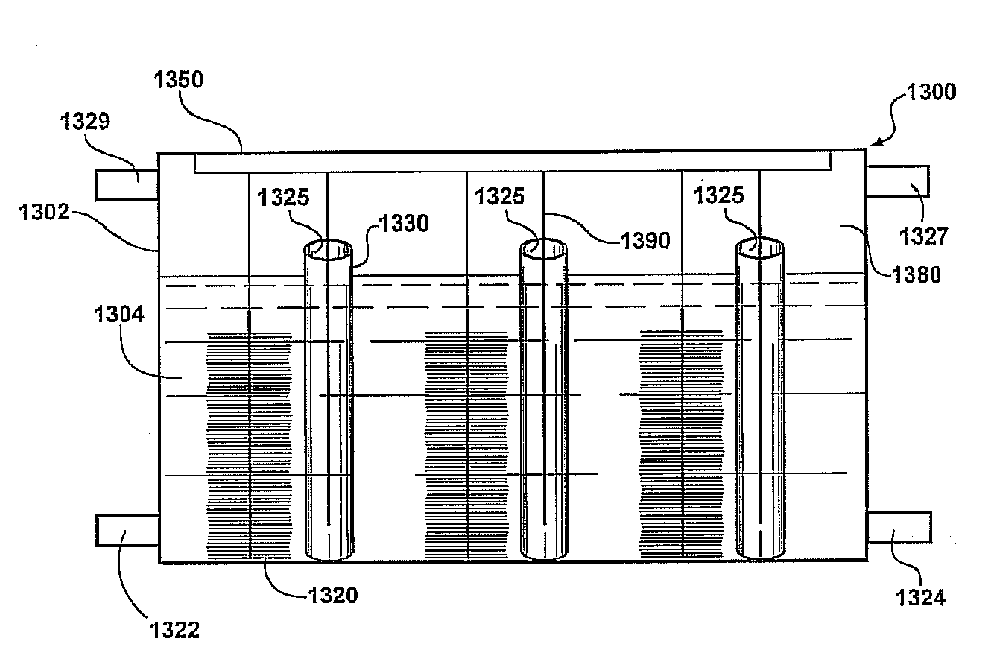
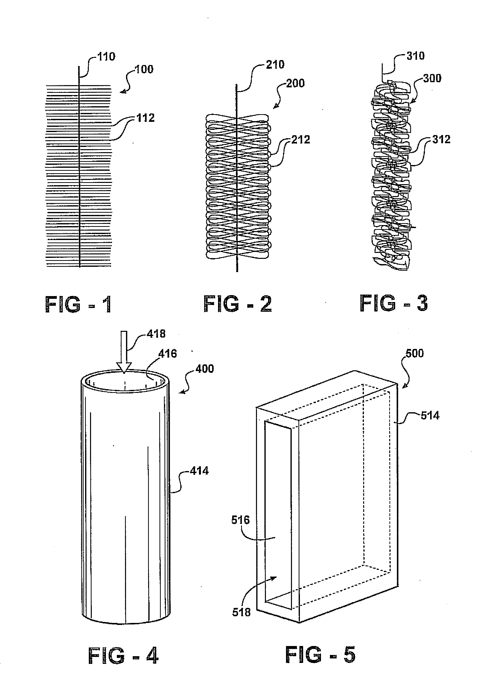
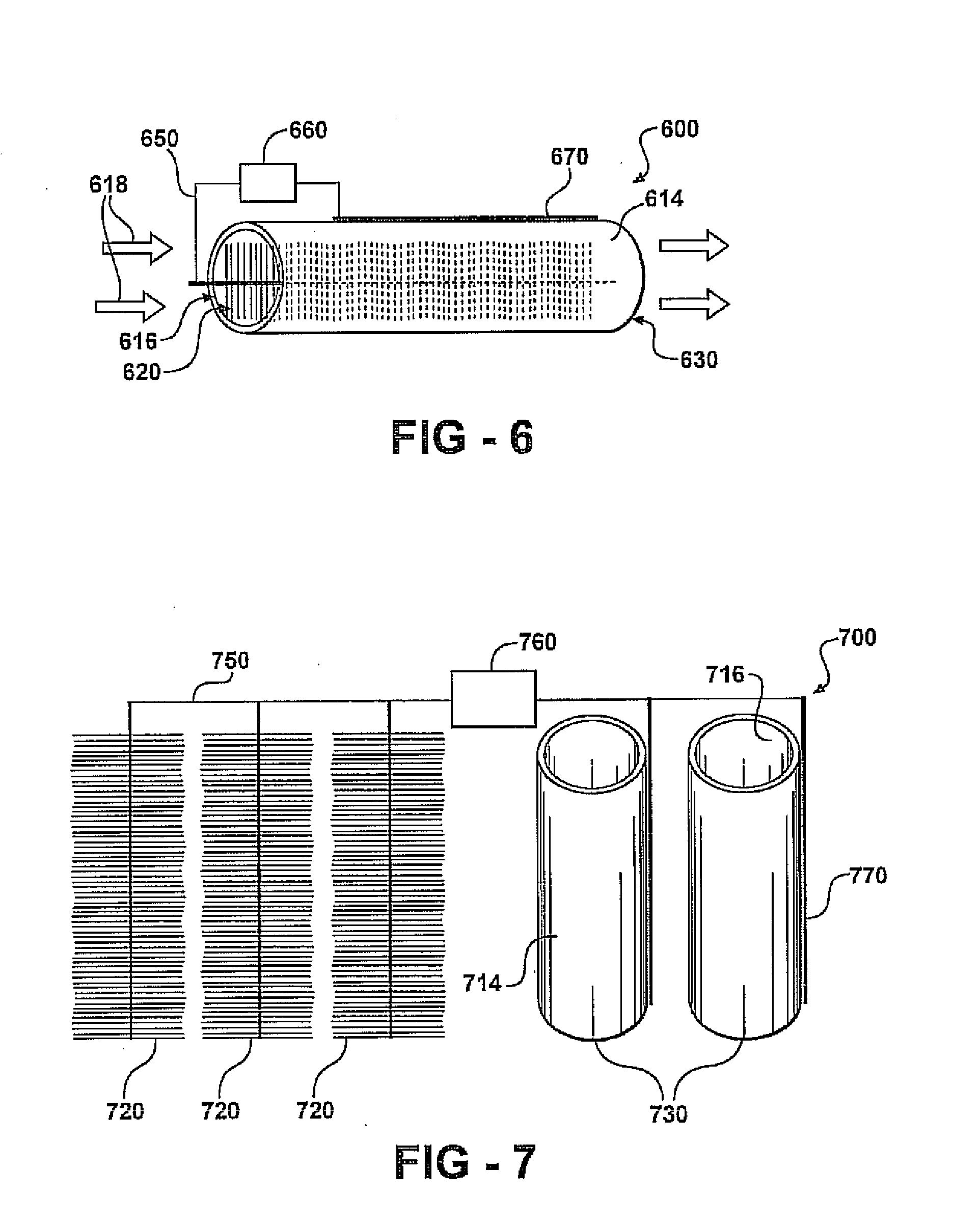
The present invention provides a microbial fuel cell with a cathode and an anode that are connected by an electrically conductive connector. The cathode is made of a membrane that forms a cylindrical wall with an internal surface and an external surface. The membrane is optionally an electrically conductive membrane. The anode is a non-toxic anodophilic bacteria-resistant slab or brick-shaped object. The membrane can be made of a nanofiltration membrane, ultrafiltration membrane, or ion exchange membrane. The membrane can also have a conductive material in electrical connection with the electrically conductive connector. The microbial fuel cell can produce hydrogen and electricity. The anode and cathode can have different shapes, and the cell can have more than one anode and / or cathode. The power source for enhancing the electrical potential between the anode and cathode can be a second microbial fuel cell or an external power source. The cathode can also have a conductive material in contact with its internal or external surface, and a catalyst for enhancing the reduction of oxygen or the hydrogen evolution reaction can be present on the membrane. The microbial fuel cell can be used to produce hydrogen and electricity.

Problems solved by technology

However, electrodes for microbial fuel cells can limit power production.

Method used


Image

  • Electrodes and methods for microbial fuel cells
  • Electrodes and methods for microbial fuel cells
  • Electrodes and methods for microbial fuel cells

Examples


example 1

[0196]Electrode Materials

[0197]In this example brush anodes are made of carbon fibers (PANEX®33 160K, ZOLTEK) cut to a set length and wound using an industrial brush manufacturing system into a twisted core consisting of two titanium wires. Two brush sizes are used in this example: a small brush 2.5 cm in outer diameter and 2.5 cm in length; and a larger brush 5 cm in diameter and 7 cm in length. Based on mass of fibers used in a single brush, and an average fiber diameter of 7.2 microns, these anodes are estimated to have a surface area of 0.22 m2 or 18,200 m2 / m3-brush volume for the small brush (95% porosity), and 1.06 m2 or 7170 m2 / m3-brush volume for the larger brush (98% porosity).

[0198]Except as noted, brush anodes are treated using ammonia gas as described in Cheng, S.; Logan, B. E. Ammonia treatment of carbon cloth anodes to enhance power generation of microbial fuel cells. Electrochem. Commun. 2007, 9, 492-496. Briefly described, ammonia gas treatment of an anode is accompl...

example 2

[0219]Cathode Preparation

[0220]An ultrafiltration hydrophilic tubular membrane (a polysulfone membrane on a composite polyester carrier) with an inner diameter of 14.4 mm (B0125, X-FLOW) and wall thickness of 0.6 mm is used as the tube-cathode. The tubes are cut to a length of 3, 6 or 12 cm (equal to a surface area of 13.5, 27 and 54 cm2) and then are coated with two coats of a commercially available graphite paint, ELC E34 Semi-Colloidal, Superior Graphite Co. Co-tetra-methyl phenylporphyrin (CoTMPP) is used as the cathode catalyst unless indicated otherwise. A CoTMPP / carbon mixture (20% CoTMPP) is prepared as described in Cheng, S. et al., Environ. Sci. Technol. 2006, 40, 364-369, and mixed with a 5% Nafion solution to form a paste using 7 microliters of Nafion per mg of CoTMPP / C catalyst. The paste is then applied to the air-facing surfaces of all tube-cathodes to achieve ˜0.5 mg / cm2 CoTMPP loading. In some tests a commercial carbon paper cathode containing Pt, 0.35 mg / cm2 of Pt ...

example 3

[0263]A plain carbon cloth (non-wet proofed, type A, E-TEK) 7 cm2 diameter was treated using ammonia gas using a thermogravimetric analyzer (TGA), Chen, W. F., et al. (2005) Carbon 43:581 (where ammonia gas is used for activated carbon to increase perchlorate removal). The furnace temperature was ramped up to 700° C. at 50° C. / min using nitrogen gas (70 mL / min) before switching the gas feed to 5% NH3 in helium gas. The sample was then held at 700° C. for 60 minutes, before being cooled back to room temperature under nitrogen gas (70 mL / min) over 120 minutes. The carbon cloth cathode contained a Pt catalyst (0.5 mg cm−2 Pt) and four diffusion layers (DLs) was prepared as described in Cheng, S., et al. (2006) Electrochem. Commun. 8, 489-494. To coat the cathode, a carbon base layer was first applied. This was prepared by applying a mixture of carbon powder (Vulcan XC-72) and 30 wt % PTFE solution (20 microliters per mg of carbon power) onto one side of the carbon cloth, air-drying at ...


PUM

PropertyMeasurementUnit
temperatureaaaaaaaaaa
diameteraaaaaaaaaa
diameteraaaaaaaaaa

Abstract

Methods of improving a performance parameter of a microbial fuel cell are provided according to embodiments of the present invention which include heating an electrode and exposing the heated electrode to ammonia gas to produce a treated electrode characterized by an increased positive surface charge on the electrode surface. Improved performance parameters include increased maximum power density, increased coulombic efficiency, increased volumetric power density and decreased microbial fuel cell operation time to achieve maximum power density

Description

REFERENCE TO RELATED APPLICATIONS[0001]This application claims priority of U.S. Provisional Patent Application Ser. No. 60 / 951,303, filed Jul. 23, 2007. This application is also a continuation-in-part of U.S. patent application Ser. No. 11 / 799,194, filed May 1, 2007, which claims priority from U.S. Provisional Patent Application Ser. No. 60 / 796,761, filed May 2, 2006. The entire content of each application is incorporated herein by reference.GOVERNMENT SPONSORSHIP[0002]This invention was made with government support under grant No. BES-0401885 awarded by the National Science Foundation. The United States government has certain rights in the invention.FIELD OF THE INVENTION[0003]The present invention relates generally to microbial fuel cells. In particular, the present invention relates to methods of increasing performance of microbial fuel cells using one or more ammonia gas treated electrodes.BACKGROUND OF THE INVENTION[0004]Recent research advances have led to the development of f...

Claims


Application Information

Patent Timeline
Patent Type & Authority Applications(United States)
IPC IPC(8): H01M8/16H01M8/04
CPCH01M4/8657H01M4/8878H01M4/8882C02F3/005H01M8/16Y02E60/527H01M4/90Y02E60/50Y02W10/37
Inventor LOGAN, BRUCECHENG, SHAOAN
Owner PENN STATE RES FOUND
Learn More