Energy storage device

a technology of energy storage and energy storage, which is applied in the direction of cell components, final product manufacturing, sustainable manufacturing/processing, etc., can solve the problems of battery failure, inability to efficiently convert sulphate back, and tendency of negative plate failure of the battery, so as to reduce the concentration of sulfuric acid solution, increase the electrode conductivity, and minimize the effect of heating

Active Publication Date: 2010-08-12
COMMONWEALTH SCI & IND RES ORG +1
View PDF101 Cites 124 Cited by
  • Summary
  • Abstract
  • Description
  • Claims
  • Application Information

AI Technical Summary

Benefits of technology

[0030]As mentioned above, during charge and discharge, part of charge received will transform to heat and gassing. Increasing electrode conductivity can minimize the heating, but not gassing. For the latter, oxygen-suppressing additives can advantageously be added to the positive plate material during paste mixing.
[0031]The effect of acid concentration on the charging ability of the positive lead dioxide electrode will be explained in detail in the Examples. The lead dioxide reacts with sulfuric acid and is converted to lead sulfate during discharge. Accordingly, the concentration of sulfuric acid solution decreases. On the other hand, the lead sulfate reacts with water and forms lead dioxide during charge. Consequently, the concentration of sulfuric acid increases. The conversion of lead sulfate to lead dioxide during charging is faster in acid solution with low concentration. Unfortunately, however, a battery using a low acid concentration gives low capacity during discharge. Thus, it has been found to be is better to use positive plate with high paste density (e.g., 4.4-4.7 g cm−3) and low volume of acid solution with specific gravity of about 1.28. Since the positive plate with high paste density will have less porosity than that with low paste density, the diffusion of acid solution either from the bulk solution to the interior of the positive plate, or from the interior of the positive plate to the bulk solution is more difficult. Thus, after discharge, the acid concentration in the interior of positive plate with high paste density will be decreased to a very low value and this will promote the charging of lead sulfate back to lead dioxide during the subsequent recharge. Furthermore, increasing paste density will reduce the porosity of the plate material. This will enhance the contact of the individual particles and, therefore, increase the conductivity of the pasted material.

Problems solved by technology

Whilst there have been many significant advances in the development of new batteries and power networks for vehicle and other applications, such batteries still suffer from a number of problems.
In early stage lead-acid batteries used in these applications, failure of the battery tended to occur at the negative plate, as a result of progressive accumulation of lead sulphate on the surfaces of the negative plates.
This occurs because the lead sulphate cannot be converted efficiently back to sponge lead during high rate recharging.
Eventually, this layer of lead sulphate develops to such an extent that the effective surface area of the plate is reduced markedly, and the plate can no longer deliver the higher current demanded from the automobile.
This significantly reduces the potential life span of the battery.
Recent improvements in the negative plates of such batteries has improved the situation to an extent that now the positive plates of the battery are likely to fail before the negative plates.

Method used


Image

  • Energy storage device
  • Energy storage device
  • Energy storage device

Examples


reference example 1

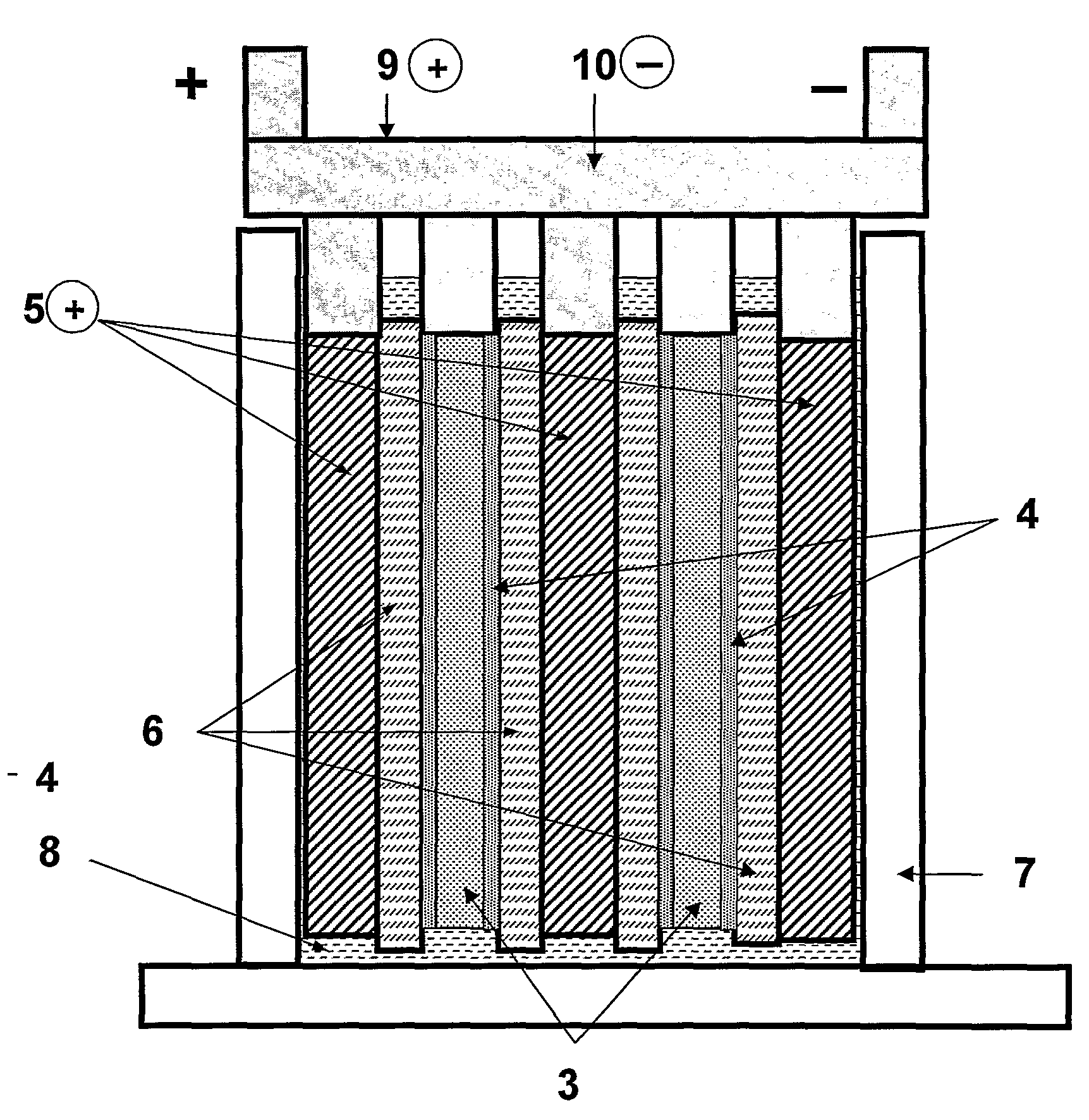
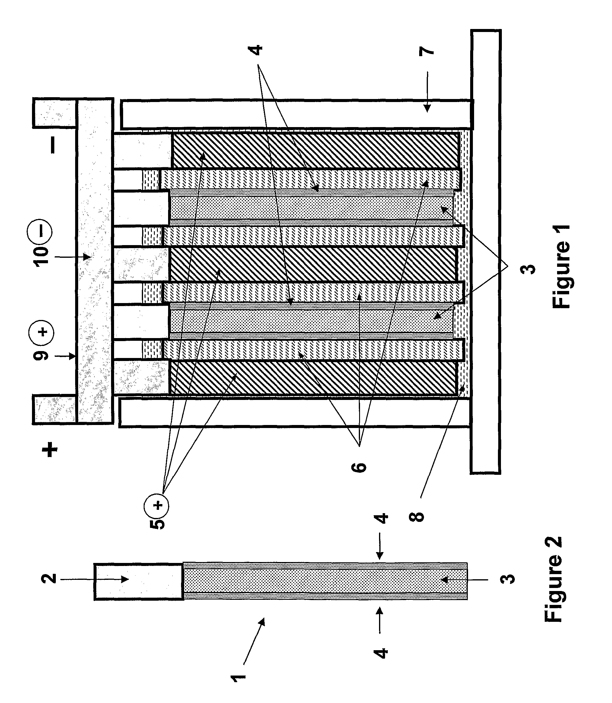
[0179]A lead-acid based energy storage device suitable for testing purposes was made in the arrangement as illustrated schematically in FIGS. 1 and 2.

[0180]The device includes two composite negative electrodes (1), which include a current collector (2) with battery negative material (3) pasted thereon, and with a coating of capacitor electrode material (4) on each face of either cured or formed negative material, forming the composite negative electrodes. The device also includes lead dioxide positive electrodes (5) which may or may not contain an additive material, depending on the experiment. The positive and negative electrodes were positioned in an alternating arrangement as illustrated in FIG. 1 in a battery case (7). The positive lead dioxide electrodes (5) can be 20-500 millimetres wide by 20-1200 millimetres high by 0.6-5 millimetres thick. The composite negative electrodes (1, comprising 3 and 4) were of the same range of width and height dimensions with that of the positiv...

reference example 2

[0200]Three cells were used for this example and were made from positive and negative plates with the same width and height dimension, namely, 102 and 107 millimetres, respectively. The thickness of positive plates in each cell was similar, namely, 1.45 millimetres, but that of the negative plate was different. Each cell composed of four positives and five negatives. Two cells were control cells (no additive in positive material and no capacitor material coating on negative plates) and had the negative-plate thickness of 1.35 millimetres. One cell was “high-performance cell” (no additive in positive material, but with capacitor material coated on both faces of the negative plates) and had the negative-plate thickness of 1.6 millimetres. Each cell had a 2-h capacity of 25 Ah. The profile used to evaluate these cells are shown in FIG. 6. This profile is used to simulate the urban driving conditions of HEV and composes of one discharge-current step and three charge-current steps. The a...

example 3

[0201]The discharge and charge processes of a positive plate and the dissolution of lead sulfate at different concentration of sulfuric acid solution are shown below and are represented in FIG. 9.

During discharge, the conversion of lead dioxide to lead sulfate proceeds via two steps. First, the lead dioxide at the positive plate reacts with HSO4− and H+ to form Pb2+, SO42− and H2O, i.e., the so-called ‘dissolution process’ (reaction 1). Then, the Pb2+ combines with SO42− to form PbSO4, i.e., the so-called ‘deposition process’ or ‘precipitation process’ (reaction 2). The first step is an electrochemical reaction and thus involves electron movement and transfer. The electrons pass from the counter negative plate into the positive plate and move to the reactive sites (i.e., lead dioxide) where the electron transfer takes place. The movement of electrons in the positive material occurs through the conductive pathways. This requires more conductive pathways in the positive material matri...


PUM

PropertyMeasurementUnit
densityaaaaaaaaaa
thicknessaaaaaaaaaa
thicknessaaaaaaaaaa

Abstract

An energy storage device comprising at least one negative electrode, wherein each negative electrode is individually selected from (i) an electrode comprising negative battery electrode material; (ii) an electrode comprising capacitor electrode material; (iii) a mixed electrode comprising either—a mixture of battery and capacitor electrode material or—a region of battery electrode material and a region of capacitor electrode material, or—a combination thereof, and wherein the energy storage device either comprises at least one electrode of type (iii), or comprises at least one electrode of each of types (i) and (ii),—at least one positive electrode, wherein the positive electrode comprises positive battery electrode material and a charging ability-increasing additive, such as one or a mixture of: (a) carbon nanomaterial, vapour grown carbon fibre, fullerene, or a mixture thereof, and (b) tin dioxide conductive materials.

Description

BACKGROUND OF THE INVENTION[0001]The present invention relates to energy storage devices, including lead-acid batteries, as well as electrodes and energy storage devices comprising such electrodes.[0002]There is growing demand for batteries that enable high current to be drawn from the battery at various stages of operation, whilst being able to supply a lower, longer term current for other stages of operation. Such batteries are also required to be able to be recharged efficiently at high and low recharge rates. Applications for such batteries include use in conventional car battery applications, electric and hybrid electric vehicles, battery-powered vehicles such as forklift trucks, renewable energy applications such as solar panels and wind turbine where auxiliary battery power is required to smooth out power supply, and standby power applications such as UPS.[0003]Whilst there have been many significant advances in the development of new batteries and power networks for vehicle ...

Claims


Application Information

Patent Timeline
Patent Type & Authority Applications(United States)
IPC IPC(8): H01M12/02H01G11/32H01G11/46H01G11/48H01M4/02
CPCH01M4/56Y02E60/13H01M4/73H01M10/06H01M10/08H01M10/4235H01M12/005H01M2004/021H01M2004/028Y02E60/126Y02T10/7016H01G11/04H01G11/12H01G11/22H01G11/32H01G11/46Y02T10/7022H01M4/62H01G11/36Y02T10/70Y02E60/10Y02P70/50
Inventor LAM, LAN TRIEUFURUKAWA, JUN
Owner COMMONWEALTH SCI & IND RES ORG
Why Eureka
Try Eureka