LIDAR Based 3-D Imaging With Varying Pulse Repetition

a 3d imaging and pulse repetition technology, applied in the field of 3d point cloud measuring systems, can solve the problems of significant source of measurement noise, inability to generate the inherently limited number of pixels such devices can generate per unit time, so as to reduce total energy consumption and heat

Active Publication Date: 2017-09-21
VELODYNE LIDAR USA INC
View PDF6 Cites 172 Cited by
  • Summary
  • Abstract
  • Description
  • Claims
  • Application Information

AI Technical Summary

Benefits of technology

[0013]Methods and systems for performing three dimensional LIDAR measurements with different pulse repetition patterns are described herein. Each repetitive pattern is a sequence of measurement pulses that repeat over time. In one aspect, the repetition pattern of a pulsed beam of illumination light emitted from a LIDAR system is varied to reduce total energy consumption and heat generated by the LIDAR system.
[0020]In some embodiments, the repetition pattern is varied based on the presence of a detected object in the three dimensional environment. In one example, the repetition pattern of a pulsed illumination beam is adjusted to reduce the number of pulses for a period of time when an object is not detected within the field of view of the pulsed illumination beam for more than a predetermined period of time. For example, when the signals detected by the detector associated with the pulsed illumination beam are negligible in value (e.g., below a threshold value) for a predetermined period of time, a controller reduces the repetition pattern of light emitted from the pulsed illumination source. In this manner, when an illumination beam is directed toward a volume of space that is devoid of objects (e.g., toward the horizon, toward the sky, etc.), energy consumption and heat generation is reduced. However, subsequently, when the signals detected by the detector associated with the pulsed illumination beam rise above the threshold value, a controller increases the repetition pattern of light emitted from the pulsed illumination source. In some examples, an object must be detected for a second, predetermined period of time after the first, predetermined period of time before controller 140 increases the repetition pattern. These thresholds prevent spurious signals from causing rapid fluctuations in the repetition pattern.

Problems solved by technology

The number of pixels such devices can generate per unit time is inherently limited due limitations on the pulse repetition rate of a single laser.
Any alteration of the beam path, whether it is by mirror, prism, or actuation of the device that achieves a larger coverage area comes at a cost of decreased point cloud density.
The detection of return signals includes significant sources of measurement noise that are exacerbated as measurement ranges are extended.
Increases in pulse rate, pulse intensity, or both, require increases in light emission, and consequent increases in energy consumption and heat generation due to energy losses associated with the light source and power electronics.
In particular, the additional heat generation is undesirable, particularly as the size of 3-D LIDAR systems continue to shrink.
However, when the illumination beam is directed toward the rear of the vehicle, the repetition pattern is varied to reduce the resolution of collected data (e.g., skip pulses, decrease repetition rate, or both).
However, for objects that are relatively close to the LIDAR device, this high sampling resolution may not be necessary to render sufficiently accurate images of close objects.

Method used


Image

  • LIDAR Based 3-D Imaging With Varying Pulse Repetition
  • LIDAR Based 3-D Imaging With Varying Pulse Repetition
  • LIDAR Based 3-D Imaging With Varying Pulse Repetition

Examples


Embodiment Construction

[0036]Reference will now be made in detail to background examples and some embodiments of the invention, examples of which are illustrated in the accompanying drawings.

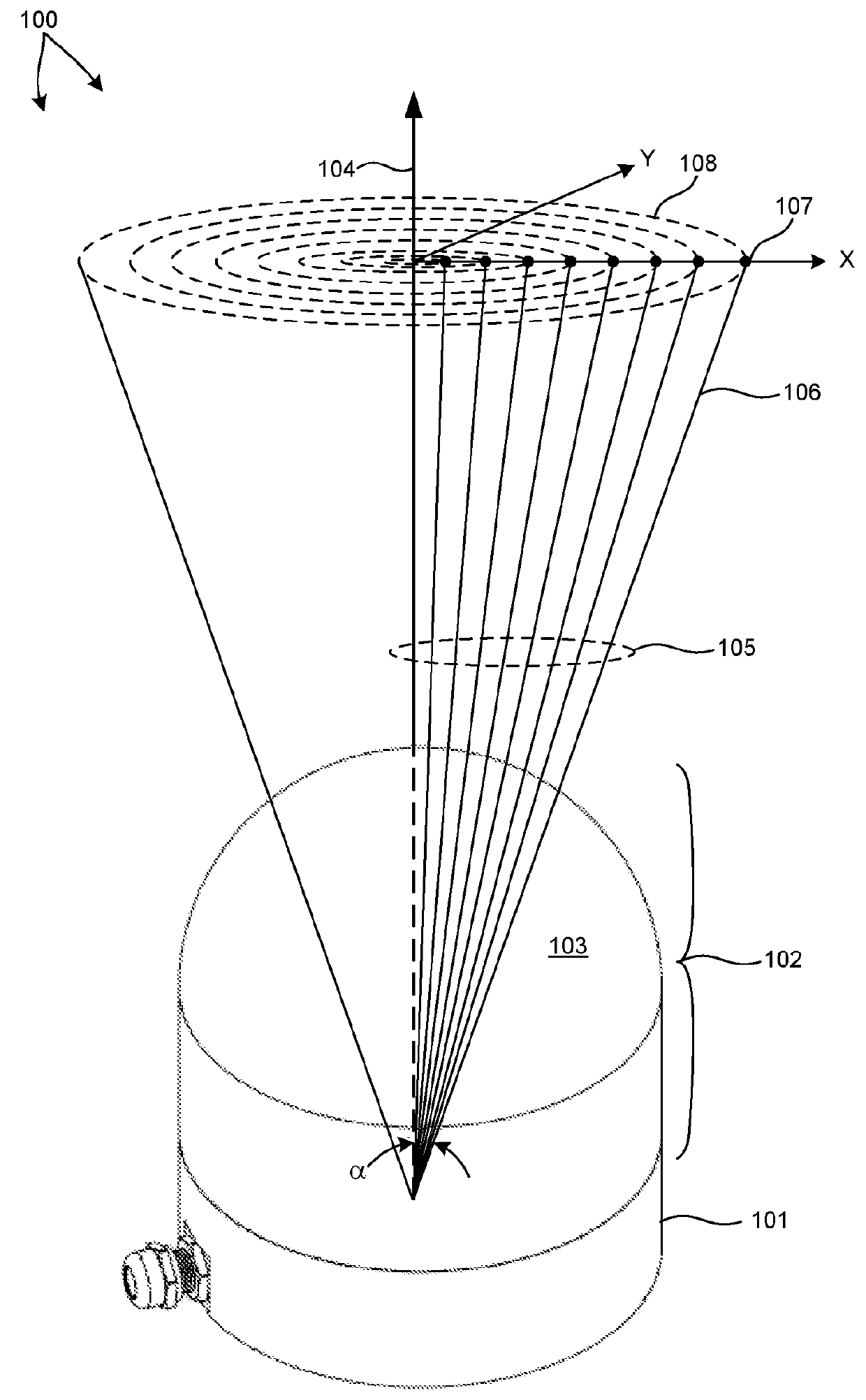
[0037]FIG. 1 is a diagram illustrative of an embodiment of a 3-D LIDAR system 100 in one exemplary operational scenario. 3-D LIDAR system 100 includes a lower housing 101 and an upper housing 102 that includes a domed shell element 103 constructed from a material that is transparent to infrared light (e.g., light having a wavelength within the spectral range of 700 to 1,700 nanometers). In one example, domed shell element 103 is transparent to light having a wavelengths centered at 905 nanometers.

[0038]As depicted in FIG. 1, a plurality of beams of light 105 are emitted from 3-D LIDAR system 100 through domed shell element 103 over an angular range, a, measured from a central axis 104. In the embodiment depicted in FIG. 1, each beam of light is projected onto a plane defined by the x and y axes at a plurality of diffe...


PUM


Abstract

Methods and systems for performing three dimensional LIDAR measurements with different pulse repetition patterns are described herein. Each repetitive pattern is a sequence of measurement pulses that repeat over time. In one aspect, the repetition pattern of a pulsed beam of illumination light emitted from a LIDAR system is varied to reduce total energy consumption and heat generated by the LIDAR system. In some examples, the repetitive pattern is varied by skipping a number of pulses. In some examples, the repetitive pattern of pulses of illumination light emitted from the LIDAR system is varied by changing a repetition rate of the sequence of emitted pulses. In some examples, the pulse repetition pattern is varied based on the orientation of the LIDAR device. In some examples, the repetition pattern is varied based on an object detected by the LIDAR device or another imaging system.

Description

CROSS REFERENCE TO RELATED APPLICATION[0001]The present application for patent claims priority under 35 U.S.C. §119 from U.S. provisional patent application Ser. No. 62 / 311,283, entitled “LIDAR Based 3-D Imaging With Varying Pulse Repetition,” filed Mar. 21, 2016, the subject matter of which is incorporated herein by reference in its entirety.TECHNICAL FIELD[0002]The described embodiments relate to LIDAR based 3-D point cloud measuring systems.BACKGROUND INFORMATION[0003]LIDAR systems employ pulses of light to measure distance to an object based on the time of flight (TOF) of each pulse of light. A pulse of light emitted from a light source of a LIDAR system interacts with a distal object. A portion of the light reflects from the object and returns to a detector of the LIDAR system. Based on the time elapsed between emission of the pulse of light and detection of the returned pulse of light, a distance is estimated. In some examples, pulses of light are generated by a laser emitter....

Claims


Application Information

Patent Timeline
Patent Type & Authority Applications(United States)
IPC IPC(8): G01S17/02H04N13/02G01S17/89G01S7/486G01S17/10G01S17/86G01S7/4865
CPCG01S7/4865G01S17/023H04N13/0253G01S17/89G01S17/10G01S17/42G01S7/4815H04N13/254G01S17/86
Inventor HALL, DAVID S.KERSTENS, PIETER J.CUI, YUPENGREKOW, MATHEW NOELNESTINGER, STEPHEN S.
Owner VELODYNE LIDAR USA INC
Why Eureka
Try Eureka