
Tank filters adaptable for placement with a guide wire, in series with the lead wires or circuits of active medical devices to enhance MRI compatibility

a technology of guide wires and tank filters, applied in the direction of feed-through capacitors, structural fixed capacitor combinations, therapy, etc., can solve the problem of very high impedance and achieve the effect of rapid imagery

Inactive Publication Date: 2008-07-03
WILSON GREATBATCH LTD
View PDF55 Cites 174 Cited by
  • Summary
  • Abstract
  • Description
  • Claims
  • Application Information

AI Technical Summary

Benefits of technology

The present invention is about novel tank filters that can be placed at various locations in the medical device lead wire system or the distal TIP to prevent or reduce current flow and associated heating. These filters work at specific frequencies to create a high impedance, which prevents current from flowing through the lead wires and into the body tissue. The filters are small in size, biocompatible, and can be designed to resonate at different frequencies to control various induced currents. The invention solves the problem of undesirable currents and associated heating in medical devices and provides a solution to reduce or eliminate harmful effects. The filters can be used in conjunction with other EMI filters to provide added protection.

Problems solved by technology

It is also well known that when a near-ideal tank filter is at its resonant frequency, it will present a very high impedance.
A major challenge for designing a tank filter for human implant is that it must be very small in size, biocompatible, and highly reliable.

Method used


Image

  • Tank filters adaptable for placement with a guide wire, in series with the lead wires or circuits of active medical devices to enhance MRI compatibility
  • Tank filters adaptable for placement with a guide wire, in series with the lead wires or circuits of active medical devices to enhance MRI compatibility
  • Tank filters adaptable for placement with a guide wire, in series with the lead wires or circuits of active medical devices to enhance MRI compatibility

Examples


Embodiment Construction

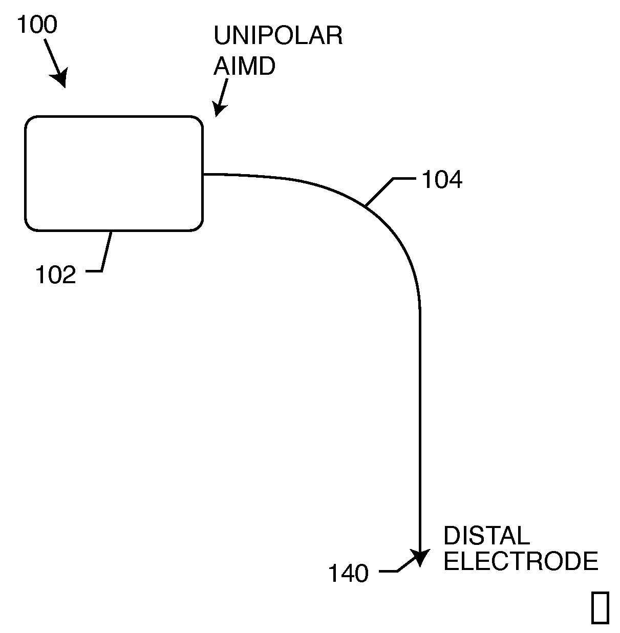
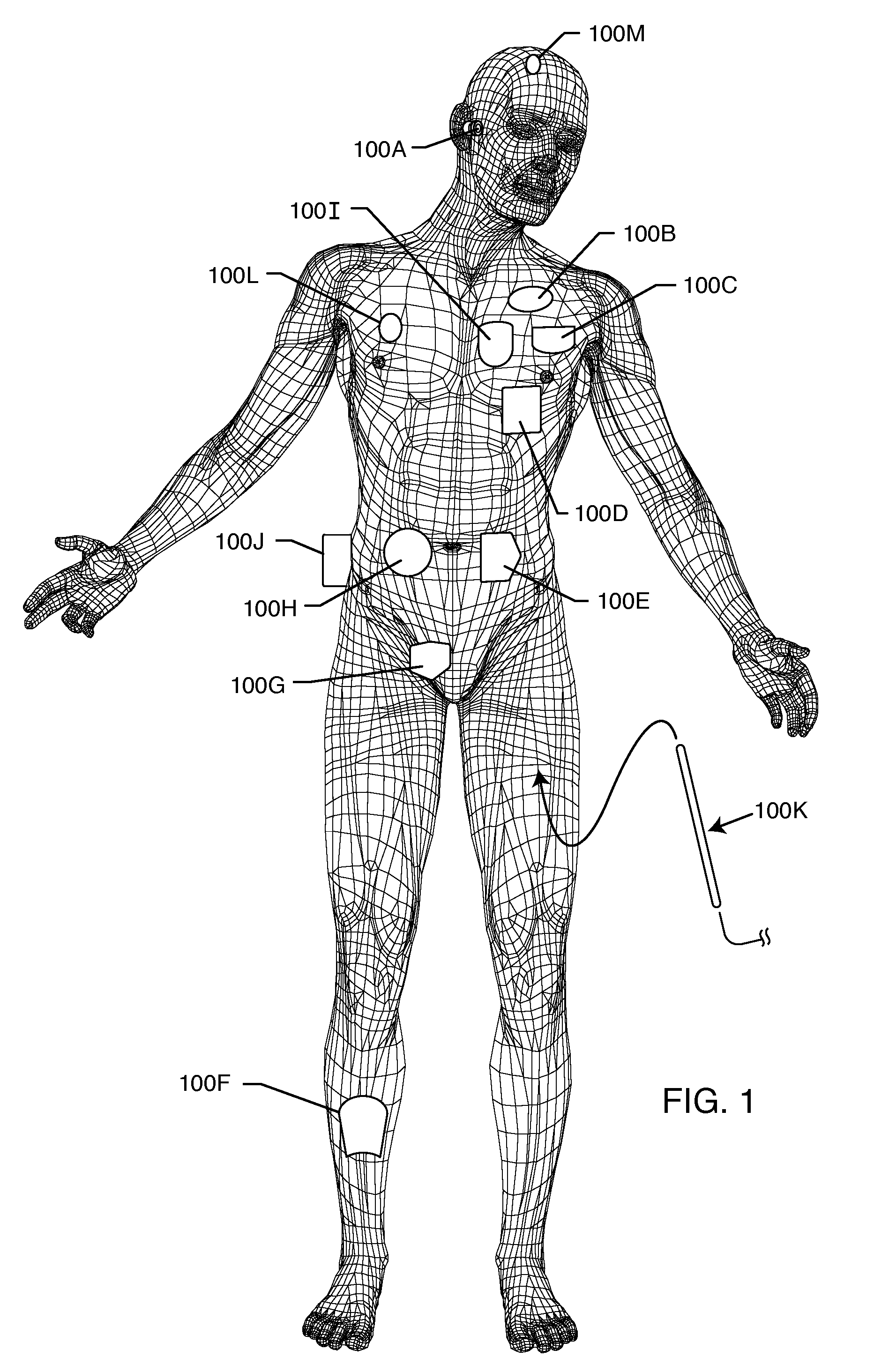
[0204]As shown in the drawings, for purposes of illustration, the present invention resides in the placement of tank filters in series with lead wires or circuits of active medical devices to protect the patient and / or medical device from undesirable electromagnetic interference signals, such as those generated during MRI and other medical procedures. The present invention also resides in the design, manufacturing, and tuning of such tank filters to be used in the lead wires or active medical devices. As will be explained more fully herein, the invention is applicable to a wide range of external medical devices, probes, catheters, monitoring lead wires and the like that may be temporarily inserted onto a patient or that a patient may be wearing or connected to during medical diagnostic procedures, such as MRI.

[0205]In the following description, functionally equivalent elements shown in various embodiments will often be referred to utilizing the same reference number.

[0206]FIG. 1 ill...


PUM


Abstract

A tank filter is provided for a lead wire of an active medical device (AMD). The tank filter includes a capacitor in parallel with an inductor. The parallel capacitor and inductor are placed in series with the lead wire of the AMD, wherein values of capacitance and inductance are selected such that the tank filter is resonant at a selected frequency. A passageway through the tank filter permits selective slidable passage of a guide wire therethrough for locating the lead wire in an implantable position. The Q of the inductor may be relatively maximized and the Q of the capacitor may be relatively minimized to reduce the overall Q of the tank filter to attenuate current flow through the lead wire along a range of selected frequencies. In a preferred form, the tank filter is integrated into a TIP and / or RING electrode for an active implantable medical device.

Description

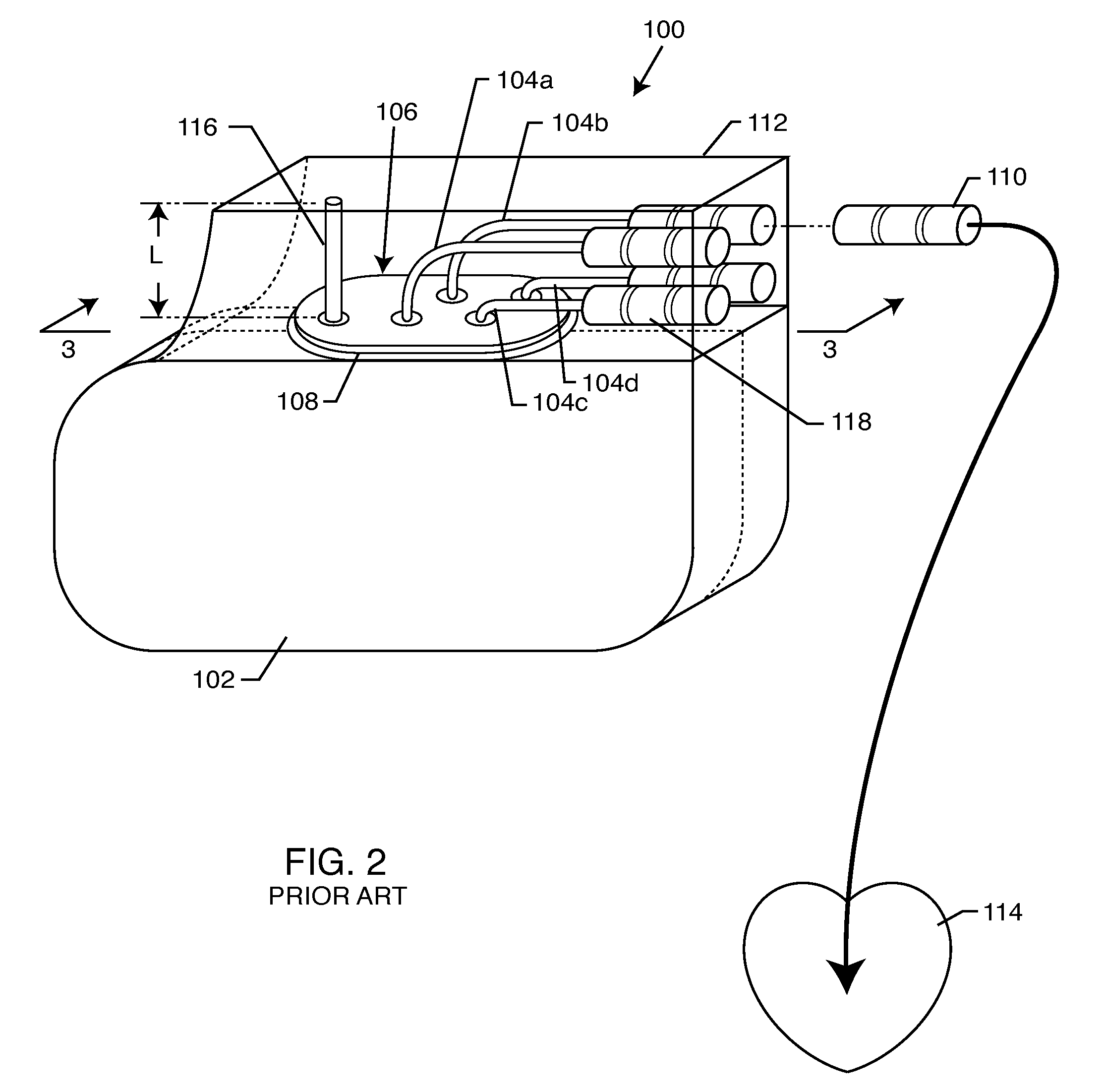
BACKGROUND OF THE INVENTION[0001]This invention relates generally to electromagnetic interference (EMI) tank filter assemblies, particularly of the type used in active implantable medical devices (AIMDs) such as cardiac pacemakers, cardioverter defibrillators, neurostimulators and the like, which raise the impedance of internal electronic or related wiring components of the medical device at selected frequencies in order to reduce or eliminate currents induced from undesirable electromagnetic interference (EMI) signals. The invention incorporates an improvement passageway through the band stop filter permitting selective slidable passage of a guide wire therethrough. The invention is also applicable to a wide variety of commercial, telecommunications, military and space applications. The present invention is also applicable to a wide range of external medical devices, including externally worn drug pumps, EKG / ECG electrodes, neurostimulators, ventricular assist devices and the like....

Claims


Application Information

Patent Timeline
Patent Type & Authority Applications(United States)
IPC IPC(8): H03H7/01A61N1/08
CPCA61N1/05A61N1/056A61N1/0565A61N1/0573A61N1/3718H03H7/1783A61N2001/086H01G4/35H01G4/40H03H7/01H03H7/1766A61N1/3754A61N1/086
Inventor STEVENSON, ROBERT A.FRYSZ, CHRISTINE A.DABNEY, WARREN S.BRENDEL, RICHARD L.
Owner WILSON GREATBATCH LTD
Learn More