Method for combined air and liquid cooling of stacked electronics components

a technology for electronics components and liquid cooling, which is applied in the direction of cooling/ventilation/heating modifications, electrical apparatus casings/cabinets/drawers, instruments, etc., can solve the problems of cooling challenge, unmanageable frame level approach, and the inability of room air conditioning to effectively handle load, so as to reduce both susceptibility to electromagnetic interference and improve characteristics

Inactive Publication Date: 2005-08-02
IBM CORP
View PDF19 Cites 200 Cited by
  • Summary
  • Abstract
  • Description
  • Claims
  • Application Information

AI Technical Summary

Benefits of technology

[0007]The invention described here, which provides an air / liquid heat removal enclosure system with electromagnetic and acoustic noise control capability for electronic equipment, is an improvement over prior art systems. The invention utilizes an enclosure scheme within which a stack or stacks of electronic drawers are packaged. Air is circulated within the enclosure to cool the electronics and is passed across one or more air-to-liquid finned-tube heat exchanger(s) (mounted to the side of the electronics in a first embodiment, and in front and / or back of the electronics in a second embodiment) to transfer the total system heat load to water which then exits the frame. Because the frame is closed and because the inner walls are lined with sound absorbent or deadening material, much of the acoustic noise caused by the air moving devices will be contained within the closed cabinet. Also, since the cabinet is closed with only minimal openings at the bottom of the frame for cables, it will also exhibit improved characteristics with respect to reducing both susceptibility to electromagnetic interference from outside the cabinet and electromagnetic radiation from within the cabinet.

Problems solved by technology

This trend poses a cooling challenge at both the module and system level.
However, this approach is becoming unmanageable at the frame level in the context of the computer installation (i.e. data center).
The sensible heat load carried by the air exiting the frame will eventually exceed the ability of the room air conditioning to effectively handle the load.
In such installations not only will the room air conditioning be challenged, but the situation may also result in recirculation problems with some fraction of the “hot” air exiting one frame being sucked into the air inlets of a nearby frame.
Furthermore, while the acoustic noise level of a powerful (or higher RPM) air moving device in a single drawer may be within acceptable acoustic limits, because of the number of air moving devices in the frame, the total acoustic noise at the frame level may not be acceptable.
In addition, the openings required in the frame for the entry and exit of air flow makes it difficult, if not impossible, to provide effective acoustic treatment to reduce the acoustic noise level outside the frame.
Finally, as operating frequencies continue to increase, we are approaching the point where electromagnetic (EMC) cross talk between tightly spaced computer frames is becoming a problem largely due to the presence of the openings in the covers required for air flow.

Method used


Image

  • Method for combined air and liquid cooling of stacked electronics components
  • Method for combined air and liquid cooling of stacked electronics components
  • Method for combined air and liquid cooling of stacked electronics components

Examples


first embodiment

[0035]the present invention uses the principle of closed air circulation heat removal and introduces an air flow configuration coupled with the placement of the heat exchanger on the side of the electronics frame; it may be preferred in that it offers the following advantages:[0036]The side-mounted heat exchanger is not readily susceptible to accidental damage due to water leakage when service is performed.[0037]The height of the frame is not extended. This is important in a room with sprinkler heads less than nine feet from the floor as there is a safety specification requiring a minimum of 18 inches from the top of the frame to the sprinkler head.[0038]Side chilled air sub-frame is shipped separately and on its own casters greatly simplifying assembly in the field.[0039]Condensation that may be produced by the air chilling heat exchanger is well away from the electronics.[0040]The positioning of the heat exchanger allows for large dimensions with an associatedly large heat removal...

second embodiment

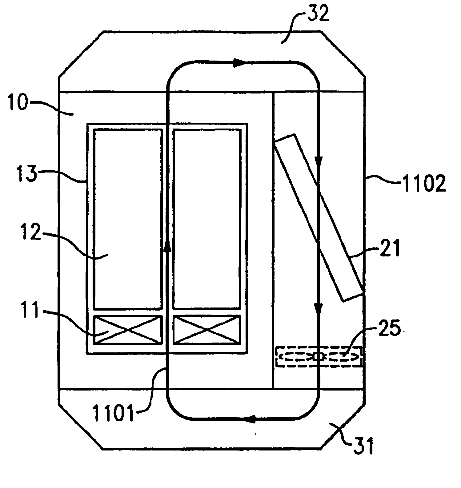
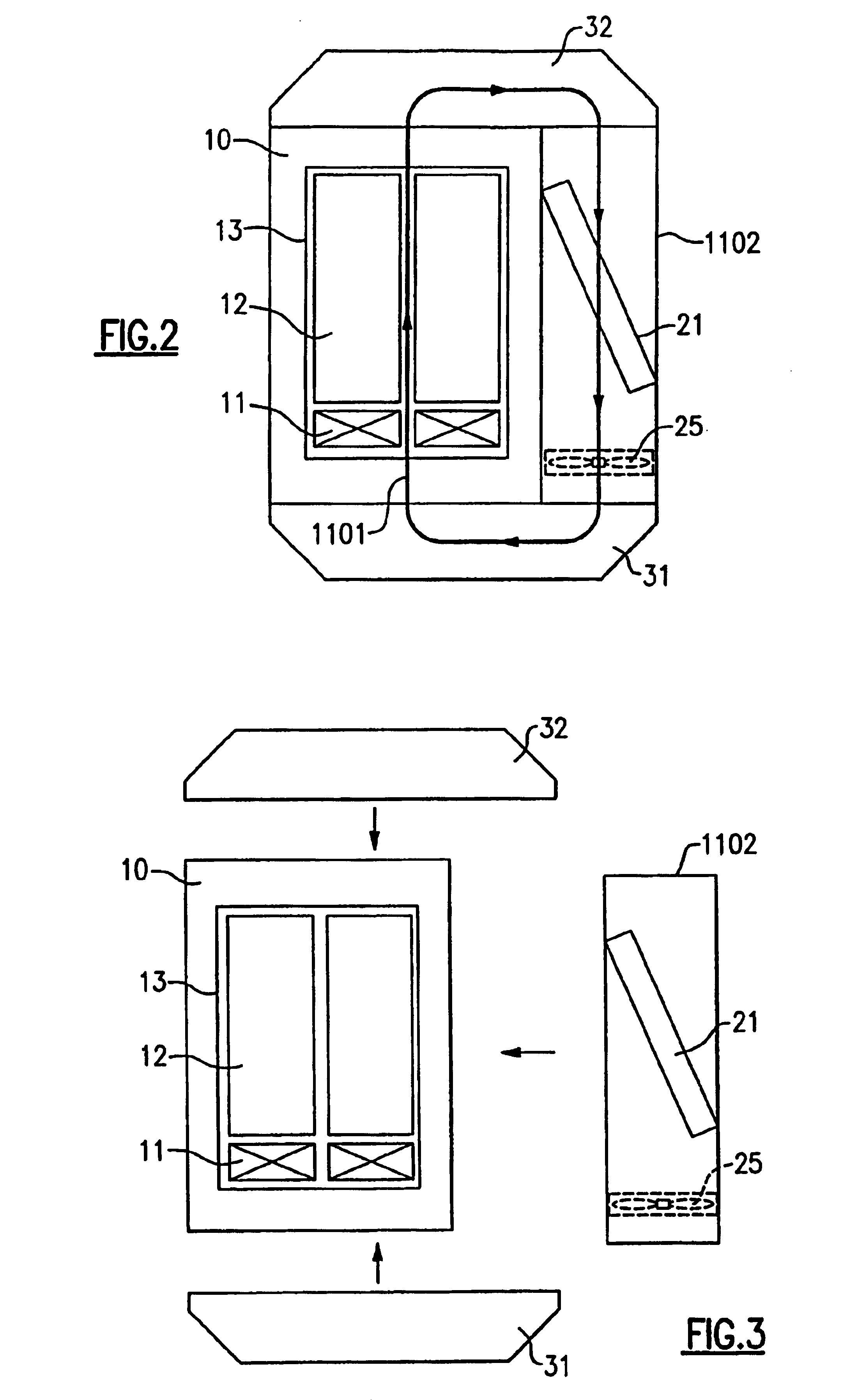
[0044]In accordance with the present invention, a cross-sectional side view of the cabinet and stack of electronic drawers is shown in FIGS. 5a and 5b. As shown in FIG. 5a, air-to-liquid heat exchangers 21 to remove heat from the closed loop air cooling stream are provided across the front (entrance) and / or back (exit) of the stack of electronics drawers. A closed air flow loop is created by the supply plenum 22, electronics drawers 13, return plenum 23, and the connecting duct 24 at the bottom of the cabinet. Although not shown, electrical cables may penetrate the connecting duct to provide signal I / O and electrical power from outside the cabinet. As shown in FIG. 5b, auxiliary fans or blowers 25 may be provided at the inlet and exit of the supply and return air plenums, respectively, to increase the total system air flow and overcome any additional pressure drops incurred due to flow through the plenums. It will be noted that a converging cross-section profile is utilized in the s...


PUM


Abstract

An enclosure apparatus provides for combined air and liquid cooling of rack mounted stacked electronic components. A heat exchanger is mounted on the side of the stacked electronics and air flows side to side within the enclosure, impelled by air-moving devices mounted behind the electronics. Auxiliary air-moving devices may be mounted within the enclosure to increase the air flow. In an alternative embodiment, air-to-liquid heat exchangers are provided across the front and back of the enclosure, and a closed air flow loop is created by a converging supply plenum, electronics drawers through which air is directed by air-moving devices, diverging return plenum, and a connecting duct in the bottom. In a variant of this embodiment, connecting ducts are in both top and bottom, and supply and return ducts are doubly convergent and doubly divergent, respectively. Auxiliary blowers may be added to increase total system air flow. The enclosure also may be provided with automatically opening vent panels to allow room air to circulate and cool in the event of an over-temperature condition. The design of the enclosure permits it to be constructed apart from the rack-mounted apparatus and subsequently attached to the rack, if desired, at the facility at which the rack had been previously operating.

Description

CROSS-REFERENCE TO RELATED APPLICATIONS[0001]This application is a divisional of U.S. patent application Ser. No. 10 / 303,284, filed Nov. 25, 2002 now U.S. Pat. No. 6,775,137 entitled “Method And Apparatus For Combined Air And Liquid Cooling Of Stacked Elecronics Components”, the entirety of which is hereby incorporated herein by reference.FIELD OF THE INVENTION[0002]The present invention relates in general to systems and methods for cooling rack-mounted assemblages of individual electronics units, such as rack-mounted computer server units.BACKGROUND OF THE INVENTION[0003]The power dissipation of integrated circuit chips, and the modules containing the chips, continue to increase in order to achieve increases in processor performance. This trend poses a cooling challenge at both the module and system level. Increased air flow rates are needed to effectively cool high power modules and to limit the temperature of the air that is exhausted into the computer center.[0004]In many large ...

Claims


Application Information

Patent Timeline
Patent Type & Authority Patents(United States)
IPC IPC(8): H05K7/20
CPCH05K7/20754H05K7/20
Inventor CHU, RICHARD C.ELLSWORTH, JR., MICHAEL J.FUREY, EDWARDSCHMIDT, ROGER R.SIMONS, ROBERT E.
Owner IBM CORP
Why Eureka
Try Eureka