Data cable and method for producing such a data cable

a data cable and data technology, applied in the field of data cables, can solve the problems of great reduction in transmission quality, and achieve the effects of robust shielding arrangement, mechanical robustness, and effective us

Inactive Publication Date: 2017-11-02
LEONI KABEL GMBH
View PDF7 Cites 0 Cited by
  • Summary
  • Abstract
  • Description
  • Claims
  • Application Information

AI Technical Summary

Benefits of technology

[0011]An essential advantage of the invention resides in particular in the fact that by virtue of the special design and arrangement of the shielding foil a particularly effective and at the same time robust shielding arrangement is achieved. The mechanical robustness, in other words in particular the robustness of the transmission parameters of the data cable with respect to bending / changing and torsion loadings, are in particular improved by virtue of the fact that the shielding foil is wound around and not attached in particular in a longitudinal manner. Such a winding arrangement is more advantageous in the mechanical respect than a longitudinally extending foil. Nonetheless, a winding arrangement in contrast offers traditionally poorer electrical characteristics since owing to the helix-type progression of the conductive layer induced currents in this case cannot dissipate in the shielding foil in the longitudinal direction of the cable but rather the currents must flow in the transverse direction. This disadvantage is however primarily avoided by folding the shielding foil and by the special overlapping arrangement so that overall a particularly robust and at the same time optimal shielding arrangement is achieved.
[0012]This is based on the observation that an unfolded foil does not have any conductive layer in the edge region and therefore sequential and overlapping windings are not contacted in an electrical manner in the overlap region. In contrast, by virtue of folding the shielding foil an edge region is formed in an advantageous manner with a defined conductive layer, namely the conductive layer that is wound around the fold and is then embodied accordingly in the edge region of the folded shielding foil. As a consequence, the upper face is connected in one winding in an electrically conductive manner and the lower face is connected in an electrically conductive manner in the subsequent winding, in other words a contacting arrangement that covers the windings is formed. As a result of these electrical contacting arrangement of sequential windings in the overlap region, induced currents can now dissipate in all directions, particularly also in the longitudinal direction of the data cable. As a consequence, the signal attenuation in particular is considerably improved, in other words reduced, particularly in the high frequency range.
[0013]It is preferred that the conductive layer is an outermost layer of the folded foil. In other words: the conductive layer faces outwards in the case of the folded shielding foil so that in this case it is possible to make contact with other conductive elements, for example with a ground wire and / or a further shielding arrangement. Above all, however, the conductive layer as the outermost layer renders it possible in a particularly simple manner to make contact in the overlap region since then automatically two sequential windings are contacted.
[0014]In an advantageous embodiment, the shielding foil is folded in the middle. In the original, unfolded state, the shielding foil is formed as a strip with a specific entire width and extends in a longitudinal direction. The term ‘folded in the middle’ is understood to mean in particular that the shielding foil is folded along the longitudinal direction at half the entire width so that the fold extends in the longitudinal direction and divides the shielding foil into two halves of equal width that lie in particular against one another in a covering manner. The two layers are then of equal width. Such a shielding foil that is folded in the middle has significant advantages when used in a winding process since the shielding foil can be provided in a particularly uniform manner on a disc in preparation for the winding process and in addition can be also be unwound in a particularly uniform manner. In the case of an unevenly folded shielding foil, in other words a foil that is not folded in the middle, there exists in contrast the risk of the shielding foil running unevenly onto the conductor, in general onto the sub-structure, and also the risk of the geometry varying in an uncontrolled manner. In contrast, a shielding foil that is folded in the middle can be applied in a smooth and controlled manner. Fundamentally, however, a shielding foil that is not folded in the middle and has layers of different widths is also suitable.
[0015]Preferably, the shielding foil is only folded once and therefore comprises only one fold. Fundamentally, however, shielding foils that have multiple folds and in particular parallel folds are also feasible and suitable.
[0016]The insulating layer generally contains an entire width that in an unfolded state has the same width as the shielding foil. In the folded state, the width of the shielding foil corresponds depending upon the position of the fold only to a part of the entire width and in the case of a middle fold to half the entire width.

Problems solved by technology

In the case of such an application, it is particularly critical that the transmission characteristics are maintained since even small changes thereto can lead to a great reduction in the transmission quality.

Method used


Image

  • Data cable and method for producing such a data cable
  • Data cable and method for producing such a data cable
  • Data cable and method for producing such a data cable

Examples


Embodiment Construction

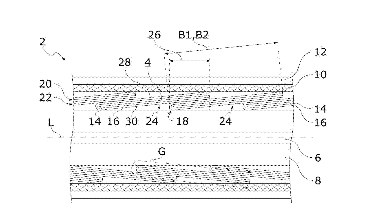
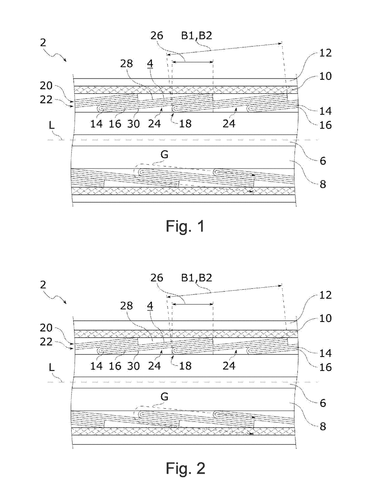
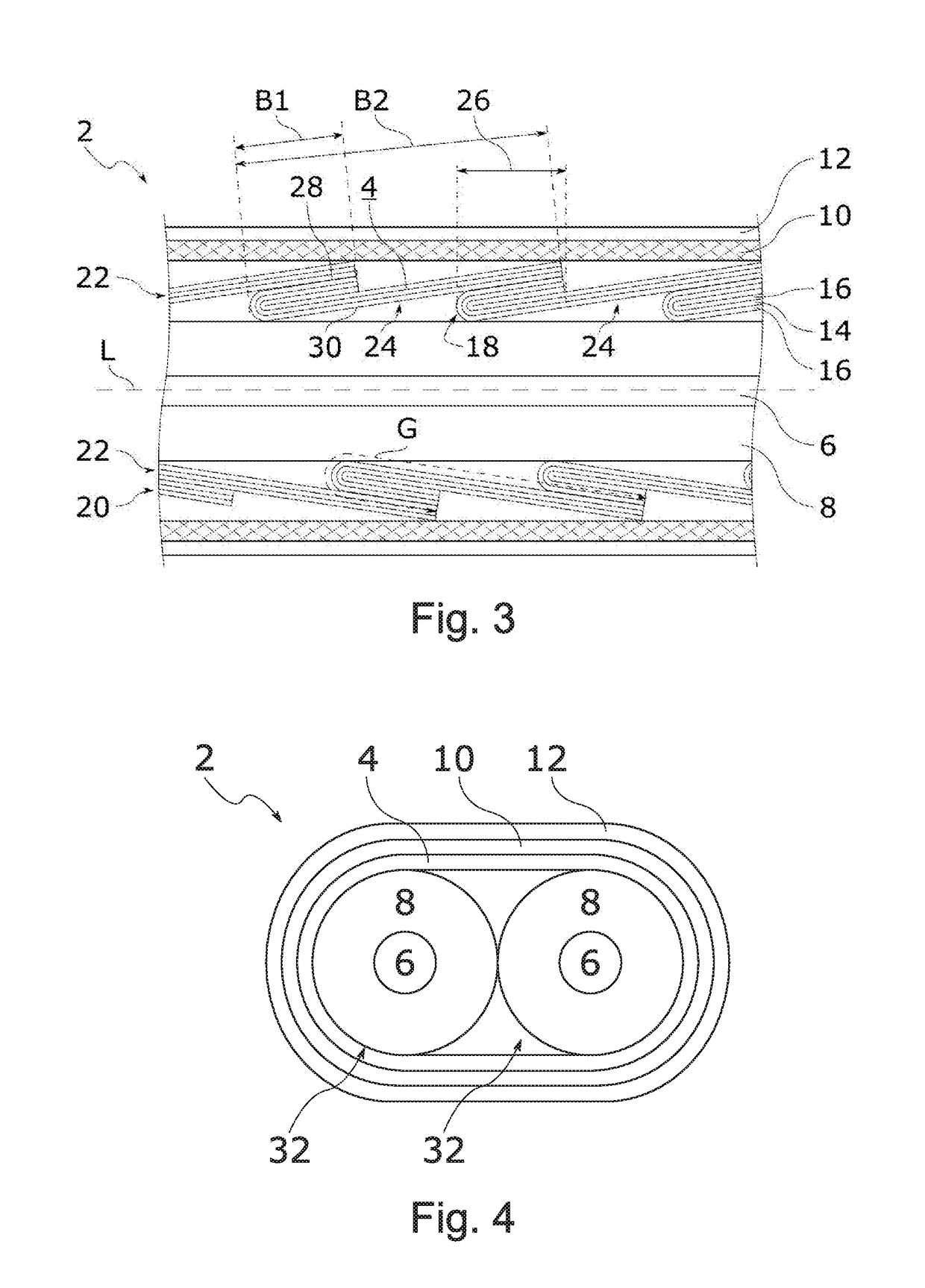
[0039]Referring now to the figures of the drawings in detail and first, particularly to FIGS. 1-3 thereof, there is shown in each case a sectional view of an exemplary embodiment of a data cable 2 along a longitudinal direction L thereof. FIG. 4 illustrates a cross-sectional view of the data cable 2 in a transverse direction with respect to the longitudinal direction L. In the case of the data cable 2, in general a folded shielding foil 4 is wound around an insulated conductor 6 in order to form a continuous shielding arrangement.

[0040]In the exemplary embodiments illustrated in FIGS. 1 to 3, the data cable is embodied as a coaxial cable for use in high speed data transmission, wherein the conductor 6 is an inner conductor that is surrounded by an insulation 8 that is used as a dielectric. The shielding foil 4 that is used in the exemplary embodiment as an outer conductor of the coaxial cable is wound directly around the dielectric. In addition, the shielding foil 4 is surrounded by...


PUM

PropertyMeasurementUnit
conductiveaaaaaaaaaa
widthaaaaaaaaaa
speedaaaaaaaaaa

Abstract

A data cable has a specially arranged and embodied shielding foil. The shielding foil surrounds an insulated conductor and has multiple layers, including a conductive layer and at least one carrier layer on which the conductive layer is applied. The shielding foil is folded and has a fold around which the conductive layer is guided so that the conductive layer forms an upper face and a lower face. The shielding foil is wound around the insulated conductor. The shielding foil has multiple sequential windings that overlap in an overlap region in which the upper face in one of the multiple sequential windings makes contact with the lower face of a following one of the multiple sequential windings so as to form a continuous shielding configuration.

Description

CROSS-REFERENCE TO RELATED APPLICATION[0001]This application claims the priority, under 35 U.S.C. §119, of German application DE 10 2016 207 322.2, filed Apr. 28, 2016; the prior application is herewith incorporated by reference in its entirety.BACKGROUND OF THE INVENTIONField of the Invention[0002]The invention relates to a data cable and a method for producing such a data cable.[0003]A data cable is used primarily for transmitting data or signals. The data cable contains for this purpose a number of usually insulated conductors by way of which electrical signals are directed. In order to improve the transmission characteristics of a data cable, in particular in the case of high frequencies, e.g. in the range of multiple Gigahertz, it is possible to shield the conductors against interference from the outside, in that the conductors are surrounded altogether, in groups or even individually by a shielding arrangement. Such a shielding arrangement is by way of example braided wire or ...

Claims


Application Information

Patent Timeline
Patent Type & Authority Applications(United States)
IPC IPC(8): H01B11/18H01B13/26H01B11/00
CPCH01B11/1826H01B13/2613H01B11/002H01B11/183H01B11/203
Inventor POEHMERER, RAINERKOEPPENDOERFER, ERWINDORNER, DOMINIKFREIMAN, SEBASTIAN
Owner LEONI KABEL GMBH
Why Eureka
Try Eureka