
Needle assembly with needle shroud and movable needle support

a technology of needle shroud and needle support, which is applied in the direction of infusion needles, intravenous devices, infusion devices, etc., can solve the problem of user's fingertip accidentally coming into contact with the rearward needle tip

Active Publication Date: 2018-03-08
OWEN MUMFORD
View PDF3 Cites 2 Cited by
  • Summary
  • Abstract
  • Description
  • Claims
  • Application Information

AI Technical Summary

Benefits of technology

This patent invention relates to a needle assembly for injection devices. The needle assembly has a needle shield and a needle support captive between the body and the shield. The needle support is mounted inside the body and can only move in one direction, so it does not need to be aware of the movement of the needle. The needle support is securely locked in place when the needle assembly is in the shrouded configuration. The needle assembly also includes a radial wall which acts as a shield to prevent accidental needle sticks. The technical effect of this invention is a needle assembly that is more robust and secure, with a reduced risk of accidental needle sticks.

Problems solved by technology

However, the internal diameter of the rearward portion of the hub is defined by the interface with the injection device and, as such, the applicant has recognised that for at least some devices the resulting opening may be of too large a diameter to prevent the risk of a user's fingertip accidentally coming into contact with the rearward needle tip.

Method used


Image

  • Needle assembly with needle shroud and movable needle support
  • Needle assembly with needle shroud and movable needle support
  • Needle assembly with needle shroud and movable needle support

Examples


first embodiment

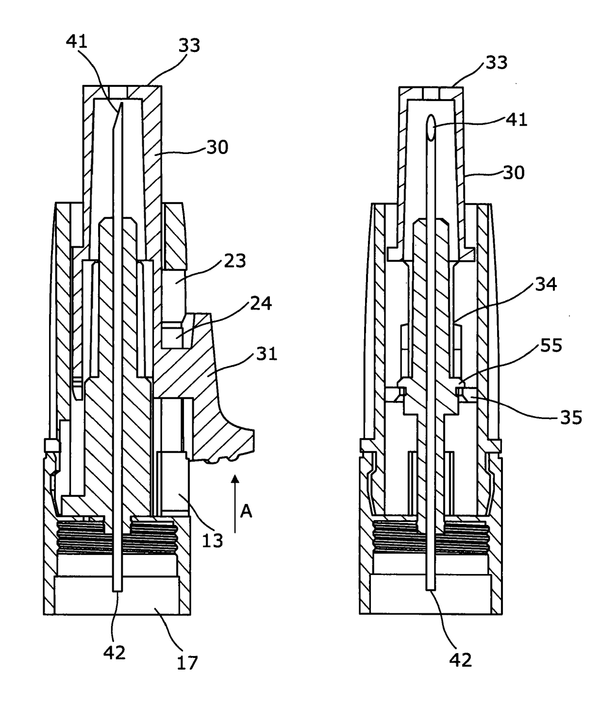
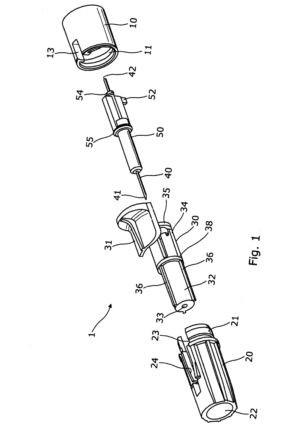
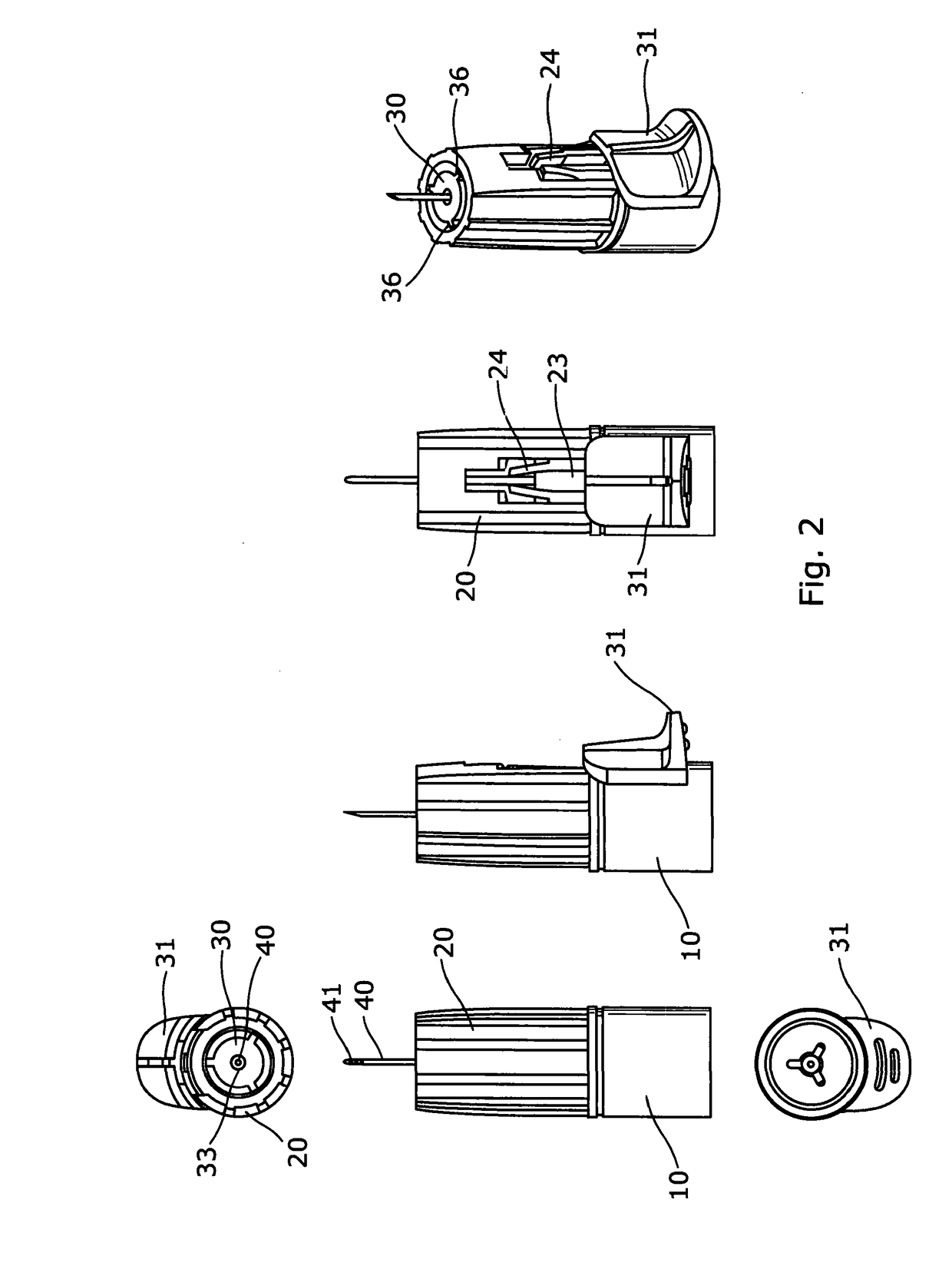
[0090]With particular reference to FIGS. 1 to 4, a needle assembly 1 in accordance with a first embodiment comprises a body, formed of a hub 10 and a forward housing 20, a shield 30, a needle 40 and a needle supporting member 50. Each of the components are generally concentrically arranged around the axis of the needle 40.

[0091]The hub 10 and forward housing 20 together define a main body of the needle assembly 1 having a generally cylindrical form. A snap fit engagement arrangement is provided between the hub 10 and forward housing 20 in the form of a recess 11 at the forward end of the hub 10 which receives a collar 21 at the rearward end of the forward housing 20.

[0092]The forward housing 20 has a generally annular profile with a bore 22 extending through the housing. An axial slot 13 / 23 is defined in the housing by a first slot portion 23 in the forward housing 20 and a second slot portion 13 in the hub 10. Two resilient members 24 are formed in the sides of the slot and are slo...

second embodiment

[0103]FIGS. 7A to 12B show a needle assembly 100 in accordance with The retractable needle assembly includes a body, formed of a forward housing portion 120 and a hub portion 110; a shield 130, a needle 140 and a needle supporting member 150. As with the earlier embodiment, each of these components is concentrically arranged around the axis A of the needle 140 (FIGS. 8A and 8B).

[0104]In this embodiment the forward housing portion 120 and the hub portion 110 are formed integrally to provide a body having a generally cylindrical form. The forward housing portion 120 has a generally annular shape with a bore 122. Two diametrically opposite projections 124 are provided at a front end of the forward housing portion 120, the projections extend out from the outer surface of the forward housing portion 120. The projections 124 have a sloped rear surface 124a, and a stepped forward surface 124b. The outer surface of the forward housing portion 120 is provided with an injection completion in...


PUM


Abstract

According to the invention there is provided a needle assembly for mounting on an injection device. The needle assembly comprises a body configured to be removably attached to an injection device in use; a double ended needle supported by the body and extending from a forward tip to a rearward tip; and a needle shield coupled to the body. The needle shield is arranged for relative axial movement with respect to the body. The needle assembly has an injection configuration, in which the shield is positioned such that the forward tip of the needle projects beyond a forward end of the shield. The needle assembly also has a shroud configuration, in which the shield is positioned such that the forward end of the shield extends beyond the forward tip of the needle. The needle assembly further comprises a needle support fixed to the needle. The needle support is captive between the body and the shield. The needle support is fixed relative to the body when the needle assembly is in the injection configuration. Movement of the shield from the injection configuration to the shroud configuration axially displaces the needle support relative to the body.

Description

FIELD OF THE INVENTION[0001]This invention relates to a needle assembly, and in particular, but not exclusively to a single-use disposable needle assembly. Such needle assemblies are typically configured for attachment to an injection device, cartridge or syringe.BACKGROUND OF THE INVENTION[0002]Injection devices, such as the Owen Mumford Autopen®, are commonly used by patients to self-administer injections of medicament. Such devices are typically provided in a pen-like body which contains, defines or receives a cartridge or syringe of medicament. The injection device generally comprises a delivery mechanism which is arranged to dispense the medicament via a needle in response to a user pressing a button or trigger.[0003]As many such injection devices are arranged to be either reusable (i.e. the cartridge of medicament can be replaced) or to deliver a plurality of separate injections until the medicament within the device has been fully consumed it is common to arrange the device t...

Claims


Application Information

Patent Timeline
IPC IPC(8): A61M5/32
CPCA61M5/3202A61M5/3213A61M5/3245A61M5/3257A61M2005/3254A61M5/32A61M5/3293A61M5/5086A61M5/3243A61M5/321A61M5/002
Inventor CALVERT, JACK
Owner OWEN MUMFORD
Learn More