
Hose band connector

a technology of hose band and connector, which is applied in the direction of coupling device connection, hoisting chain, hanging chain, etc., can solve the problems of corresponding long cutter down time, and achieve the effect of robust arrangemen

Active Publication Date: 2011-08-09
BAUER MASCH GMBH
View PDF14 Cites 1 Cited by
  • Summary
  • Abstract
  • Description
  • Claims
  • Application Information

AI Technical Summary

Benefits of technology

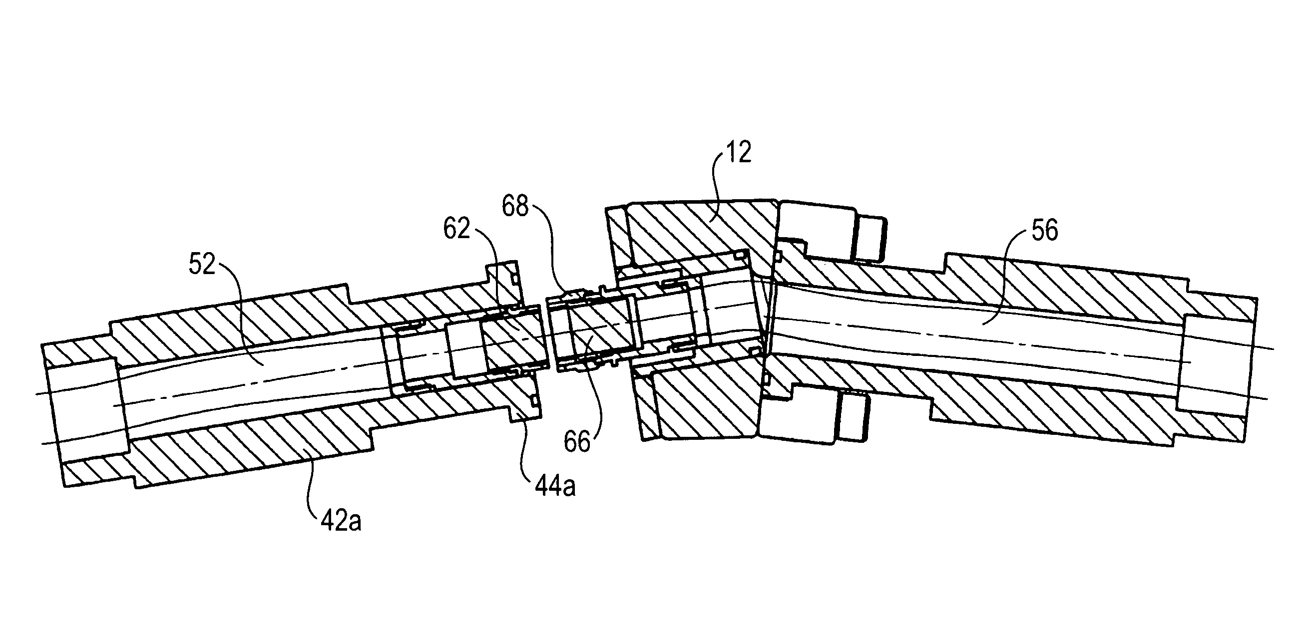
[0012]The arrangement according to the invention allows an electric line to now be directly integrated into the hose band. The risk of damage is hereby reduced. It also continues to be possible to change hose band elements in segments in case of damage to either a fluid hose or the electric line.
[0019]It is thereby particularly advantageous that a fixing device for an electric line is provided on the cover member. In this way, mechanical fixing of the electric line to the flange carrier can be realised. Additional stability is hereby achieved for the electric line.
[0023]A particularly robust arrangement is produced according to the invention in that at least one electric line is surrounded by a hose with a connection element which can be fixed with a flange element. The actual electric line can be provided in particular in a hose which corresponds to a fluid hose. The shell of the hose thus constitutes an additional protection for the electric cable against damage, which is advantageous in particular when using construction equipment, in particular with trench wall cutters.

Problems solved by technology

This is time-consuming and leads to a correspondingly long down time of the cutter.

Method used


Image

  • Hose band connector
  • Hose band connector
  • Hose band connector

Examples


Embodiment Construction

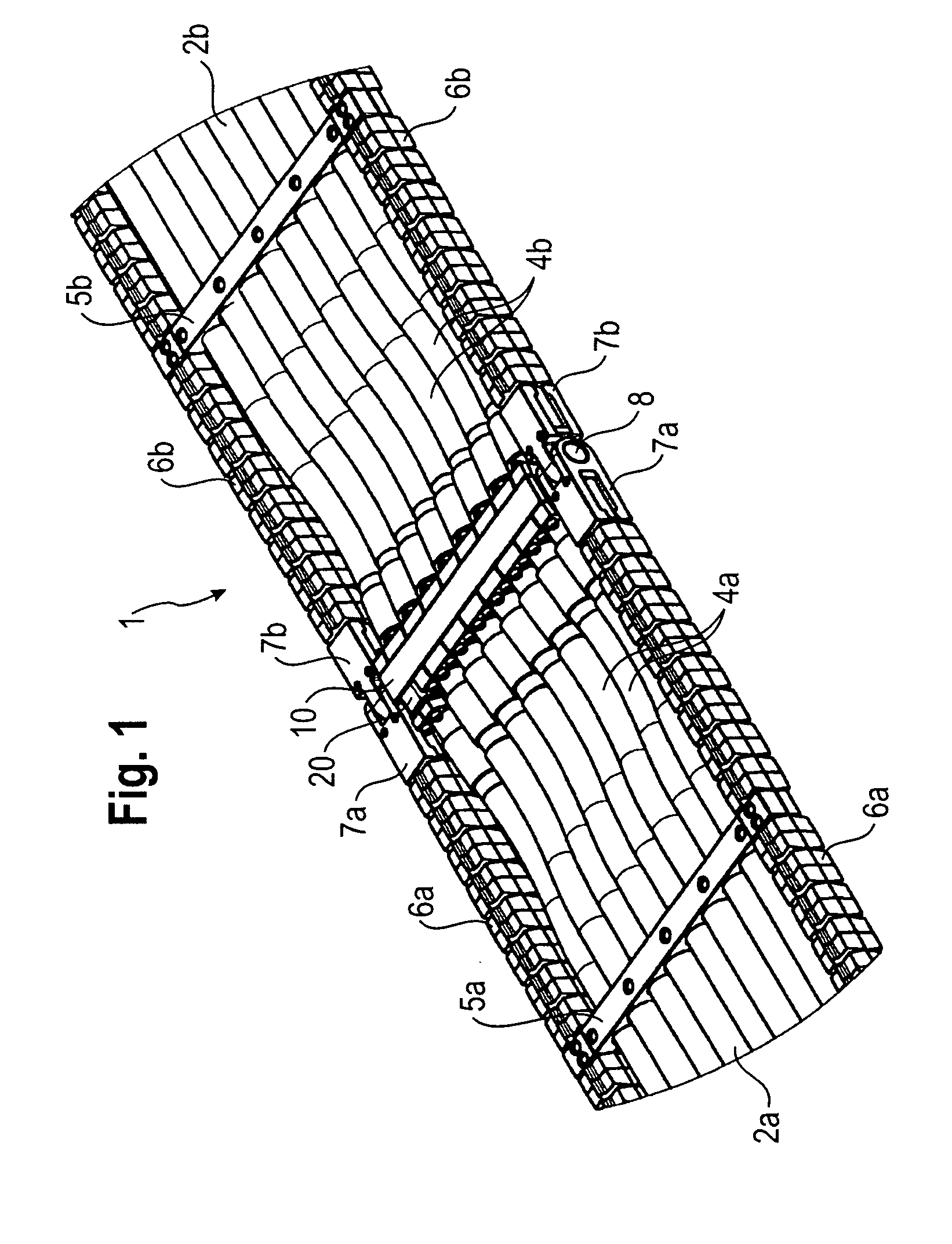
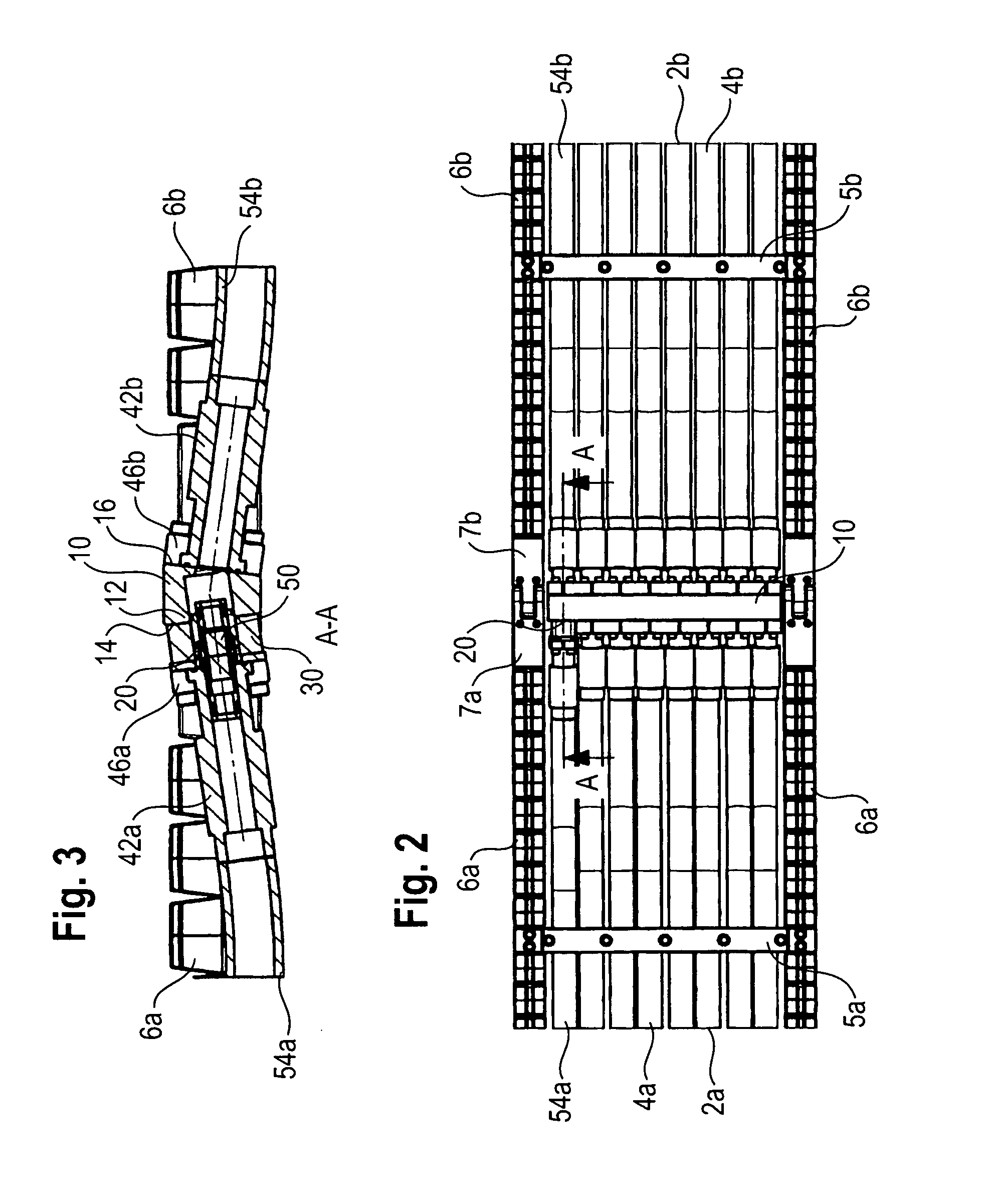
[0032]According to FIGS. 1 and 2, a hose band 1 according to the invention is formed from at least two hose band elements 2a, 2b, which each comprise a plurality of hoses 4a, 4b arranged one beside the other. The hoses 4a, 4b, arranged in a band or a strip, for conveying a fluid, in particular a hydraulic fluid, are arranged fixed at regular distances from each other via transverse webs 5a, 5b. On both sides of the strip arrangement of the hoses 4a, 4b, chain-like lateral guides 6a, 6b are provided. These consist in the known way of block-form guide elements with upwardly orientated nose elements and corresponding recesses on their lower side. The recesses on the lower side cannot be seen in FIG. 1. The chain-like lateral guides 6a, 6b allow guided rolling, whereby the individual blocks serve as spacers and thus prevent crushing of the hoses 4a, 4b.

[0033]The two hose band elements 2a, 2b are connected to each other via a hose band connector 10 according to the invention. The ends o...


PUM


Abstract

The invention relates to a hose band connector for connecting hose band elements, which each comprise a plurality of hoses for lines arranged in a band or strip. The hose connector comprises a flange carrier with two connecting sides as well as fixing devices, with which the hoses are flanged to the connecting sides. According to the invention at least one receiving element for a plug-type connection between a first electric line and a second electric line is formed on the flange carrier.

Description

BACKGROUND OF THE INVENTION[0001]1. Field of the Invention[0002]The invention relates to a hose band connector for connecting hose band elements which each comprise a plurality of hoses, arranged in bands or strips, for lines.[0003]2. Description of Related Art Including Information Disclosed Under 37 CFR §§1.97 and 1.98[0004]Such hose band connectors comprise a flange carrier which comprises a first connecting side and a second connecting side, between which passages are formed for the line connection, and fixing devices on the first connecting side and the second connecting side for flange connection of the hoses of the hose band elements.[0005]EP 0 518 292 B1 discloses a trench wall cutter with a hose band line, which is constructed from hose band elements by means of generic hose band connectors. The respective connection elements of the fluid line hoses are flanged to the two connecting sides of the strip-form hose band connector.[0006]The band or strip like arrangement of the ...

Claims


Application Information

Patent Timeline
Patent Type & Authority Patents(United States)
IPC IPC(8): H01R4/60E02F9/22
CPCF16L25/01H01R13/005F16G13/16F16L21/08F16L23/02F16L27/02
Inventor ARZBERGER, MAXIMILIANHERRMANN, CHRISTIAN
Owner BAUER MASCH GMBH
Learn More