Pump assembly

a technology of pump assembly and assembly plate, which is applied in the field of pump assembly, can solve the problems of electrical clockwork, electrical clockwork, and mechanical switch that require some manufacturing effort, and achieve the effect of saving electrical energy

Active Publication Date: 2016-12-06
GRUNDFOS HLDG
View PDF31 Cites 0 Cited by
  • Summary
  • Abstract
  • Description
  • Claims
  • Application Information

AI Technical Summary

Benefits of technology

[0005]Against this background, it is the object of the invention to provide a pump assembly of the known type, which on the one hand has the advantage of good readability, a simple operability and the robustness of a mechanical time switch, but on the other hand has the advantages of an electronic, in particular digital time switch.

Problems solved by technology

However, the disadvantage thereby is the fact that the mechanical clockwork as well as the mechanical switch require some effort with regard to manufacture and are prone to error.
Moreover, the electrical clockwork requires energy.
A disadvantage of these time switches however is the fact that the setting and programming as a rule is only possible after careful study of the operating instructions.
Moreover, the display is comparatively costly and is also prone to breakdown, in particular with humid room atmospheres.
With a failure of the display, the pump assembly may practically no longer be used independently of its switch function.

Method used


Image

  • Pump assembly
  • Pump assembly
  • Pump assembly

Examples


Embodiment Construction

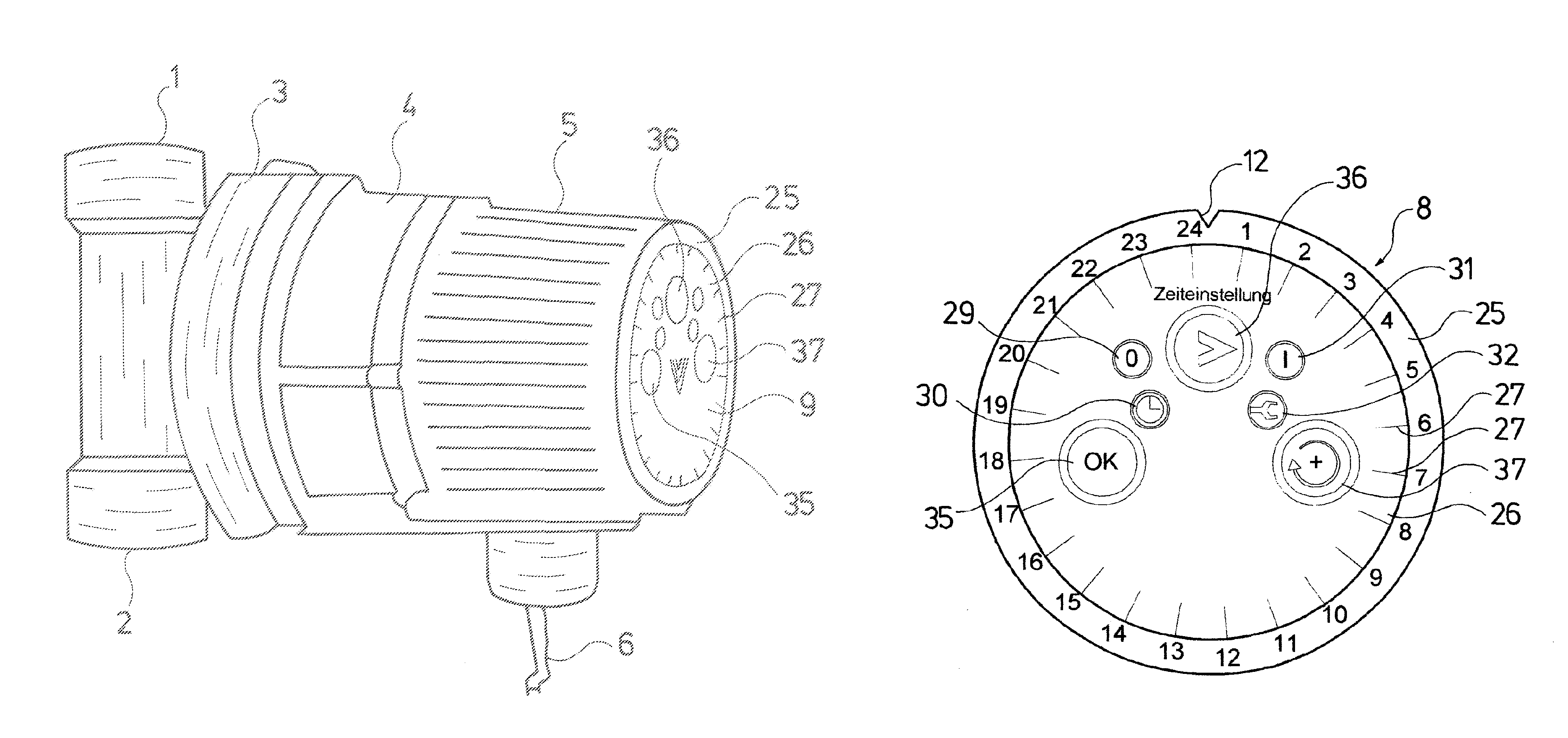
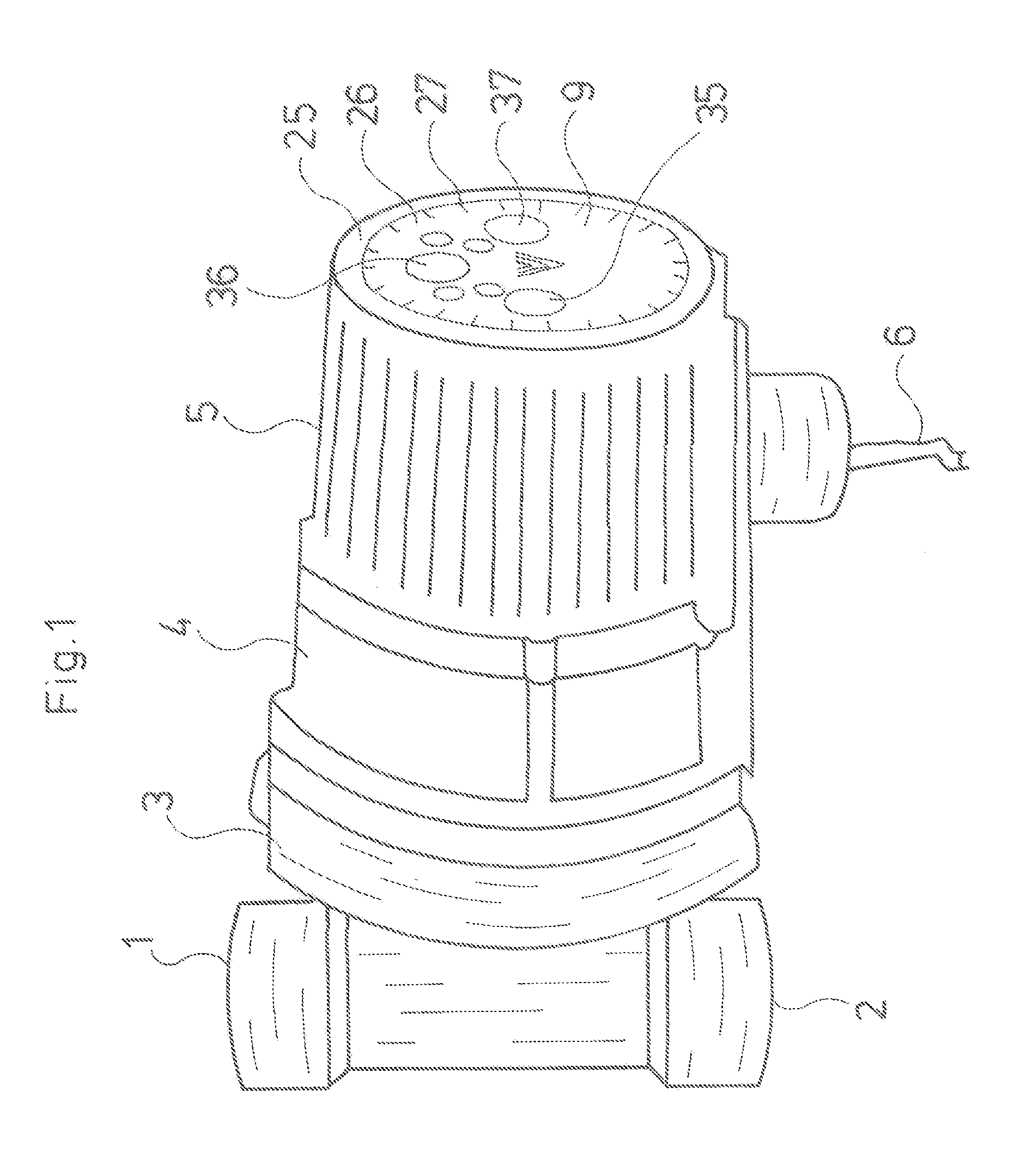
[0031]With regard to the pump assembly represented in FIG. 1, it is the case of a hot water circulation pump for incorporation into a circulation conduit with conduit connections 1 and 2 which are provided for this and which form part of a pump housing 3, in which an impeller which is not visible in the drawing is arranged in the known manner and is seated on a shaft which forms a part of a canned motor, whose motor housing in FIG. 4 connects axially onto the pump housing, and specifically on the opposite side which is away from the conduit connections 1 and 2. A spherical motor is installed in the pump assembly represented in FIG. 1, but a common canned motor may also be applied.

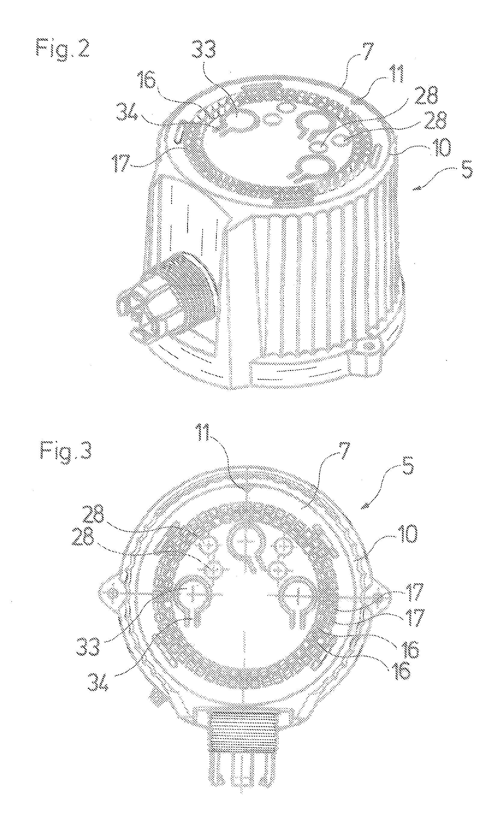
[0032]A housing 5 which forms a control and connection housing 5, connects to the motor housing 4 in an oppositely lying manner and away from the pump housing 3. This control and connection housing receives the motor control as well as the frequency converter electronics and simultaneously forms the connect...


PUM


Abstract

A pump assembly includes a centrifugal pump driven by an electric motor and is provided with a time display which is formed by an annular row of light diodes, wherein a time is assigned to each light diode.

Description

BACKGROUND OF THE INVENTION[0001]Embodiments of the invention relates to a pump assembly with the features specified below. Such pump assemblies are known and are mostly applied as circulation pumps for hot potable water circulation. Since the hot water circulation is typically only required for a brief period, specifically mostly only during the day and often also only at specific times, it is common in a few heating installation controls, to switch off the circulation pump in times, in which it is not required, in order in this manner to reduce the heat losses in the circulation conduit.[0002]For circulation pumps which are applied in an independent manner, it is counted as belonging to the state of the art to provide a time control on the pump itself, so that at the pump itself, one may set the times at which the pump is switched on, and the times at which the pump is switched off. Such a pump is, for example, described in “Grundfos Circulation Pump Comfort UP 15-14 BUT”. With re...

Claims


Application Information

Patent Timeline
Patent Type & Authority Patents(United States)
IPC IPC(8): F04D15/00G04C23/00G04G15/00G04G9/02F04D13/06
CPCF04D15/00F04D13/0686G04C23/00G04G9/02G04G15/006F04D13/06
Inventor BLASER, GEORGKEHRBAUM, JENS
Owner GRUNDFOS HLDG
Why Eureka
Try Eureka