

Clamping device for an operation
A technology of clamping device and protrusion, which is applied in the direction of hypodermic injection equipment, flow control, non-electric variable control, etc., can solve the clamping range (the clamping range is narrowed, the inner cavity of the tube cannot be fully blocked, and the blocking is not enough). Sufficient and other issues
- Summary
- Abstract
- Description
- Claims
- Application Information
AI Technical Summary
Problems solved by technology
Method used
Image

Examples
Embodiment Construction
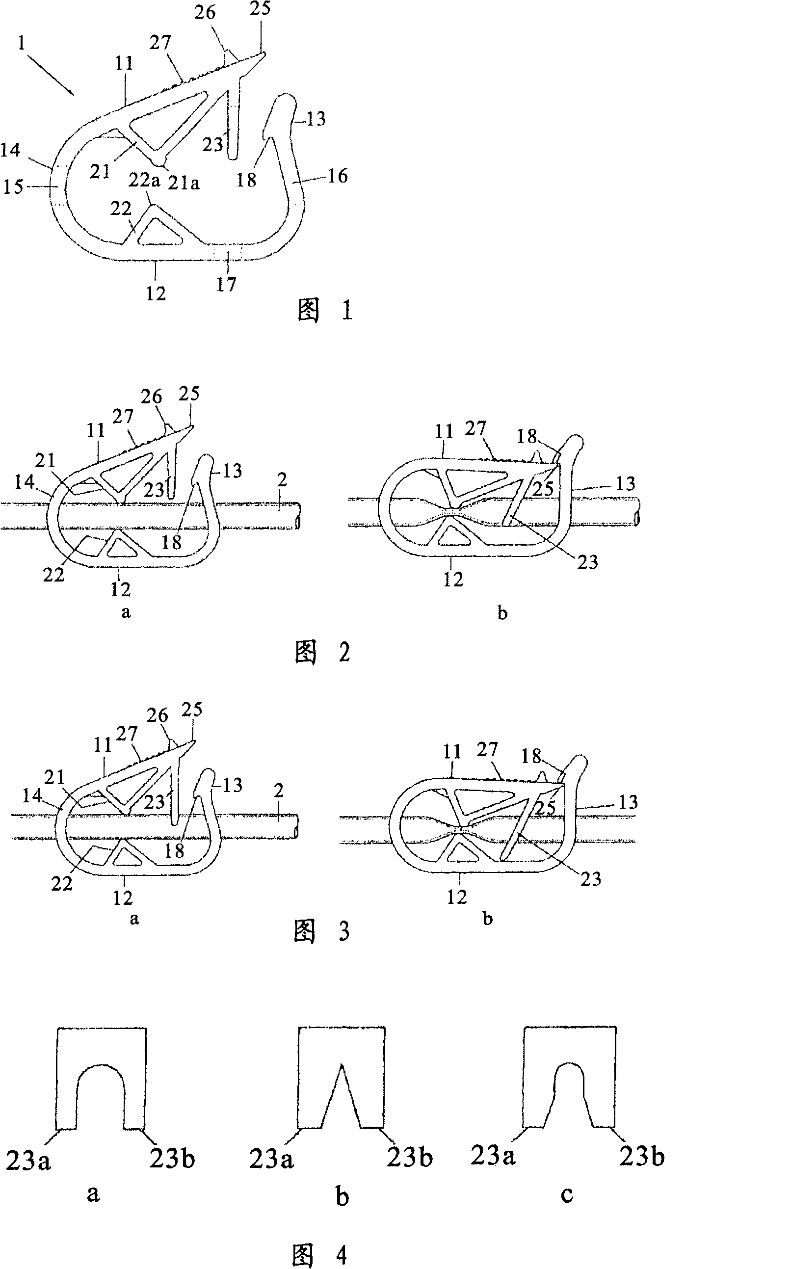
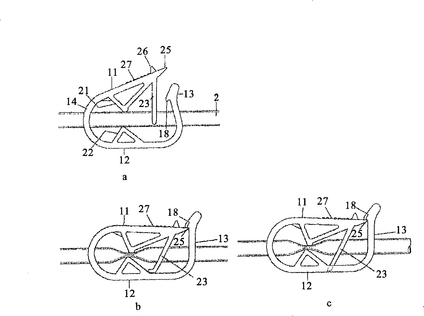
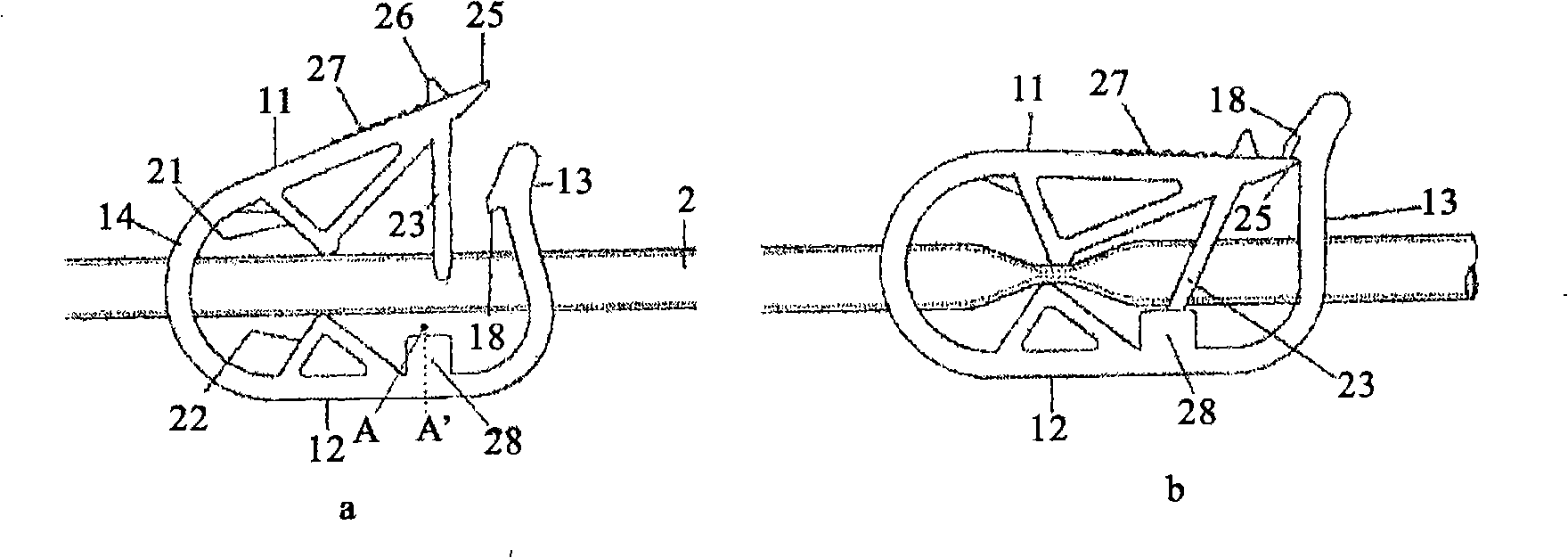
[0041] The present invention will be specifically described below with reference to the drawings, but the present invention is not limited to the specific examples described below. Fig. 1 is a side view showing a clamping device of the present invention. In Fig. 1, the clamping device of the present invention connects the upper end portion 11, the bent portion 14 provided with the pipe insertion hole 15, the bottom portion 12, the standing end portion 13 provided with the pipe insertion hole 16, and at the front end portion of the upper end portion 11 It has locking protrusions 25 . On the other hand, on the front end side of the standing end portion 13, there is a locking groove portion 18 inside, and the locking groove portion 18 is detachably engaged with the above-mentioned locking protrusion portion 25 to form an annular body. Inside the annular body, there is a first protruding portion 21 extending downward under the upper end portion 11 , and a second protruding portio...
PUM
 Abstract
Description
Claims
Application Information