Eureka AIR delivers breakthrough ideas for toughest innovation challenges, trusted by R&D personnel around the world.

Bottle embryo taking out and cooling system

A technology of cooling system and preform, applied in the field of preform take-out and cooling system, which can solve the problems of shortened preform production cycle time, unstable repeated positioning of the end point, and affecting the stability of the production system, so as to shorten the molding cycle time and shorten the Cooling time, simple structure and reasonable effect

Active Publication Date: 2014-05-28
GUANGDONG YIZUMI HIGH SPEED PACKAGING SYST COMPANY
View PDF9 Cites 3 Cited by
  • Summary
  • Abstract
  • Description
  • Claims
  • Application Information

AI Technical Summary

Problems solved by technology

[0006] However, because the three-station manipulator is relatively bulky, especially when it is applied to a mold with more than 96 cavities, the removal of the jig is larger and heavier, and the required speed is very high, so the control is very difficult, and the cost of the entire control system is very high.
In addition, due to the large load of the three-station manipulator, the repeated positioning of the end point is unstable, which affects the stability of the preform, and there will be a probability of embryo leakage, which affects the stability of the production system; and with the development of society, the needs of customers make preforms The production cycle time is continuously shortened, and the existing three-station manipulator is difficult to meet the needs of customers

Method used


Image

  • Bottle embryo taking out and cooling system
  • Bottle embryo taking out and cooling system
  • Bottle embryo taking out and cooling system

Examples


Embodiment Construction

[0041] The present invention will be further described below in conjunction with the accompanying drawings and embodiments.

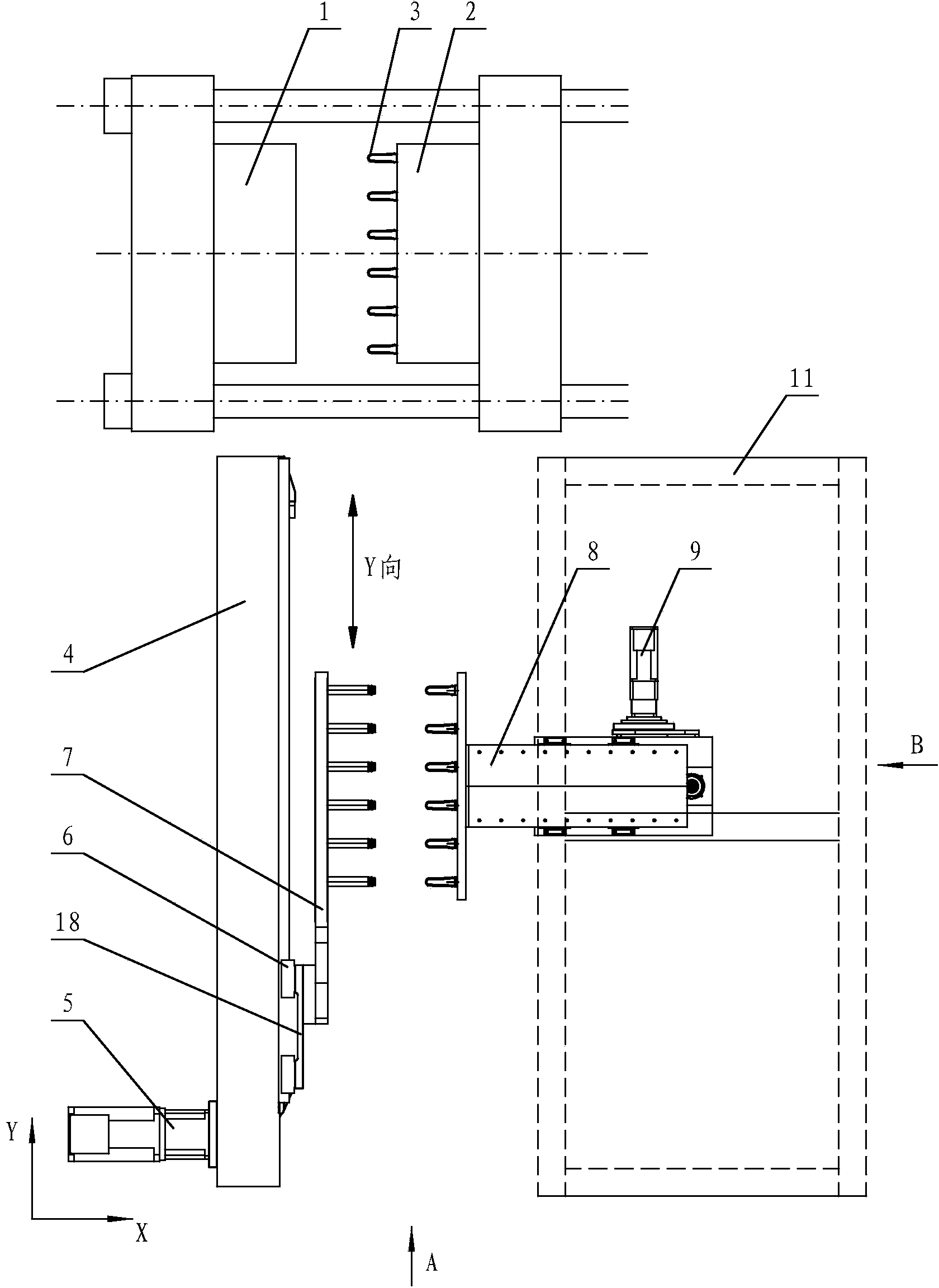
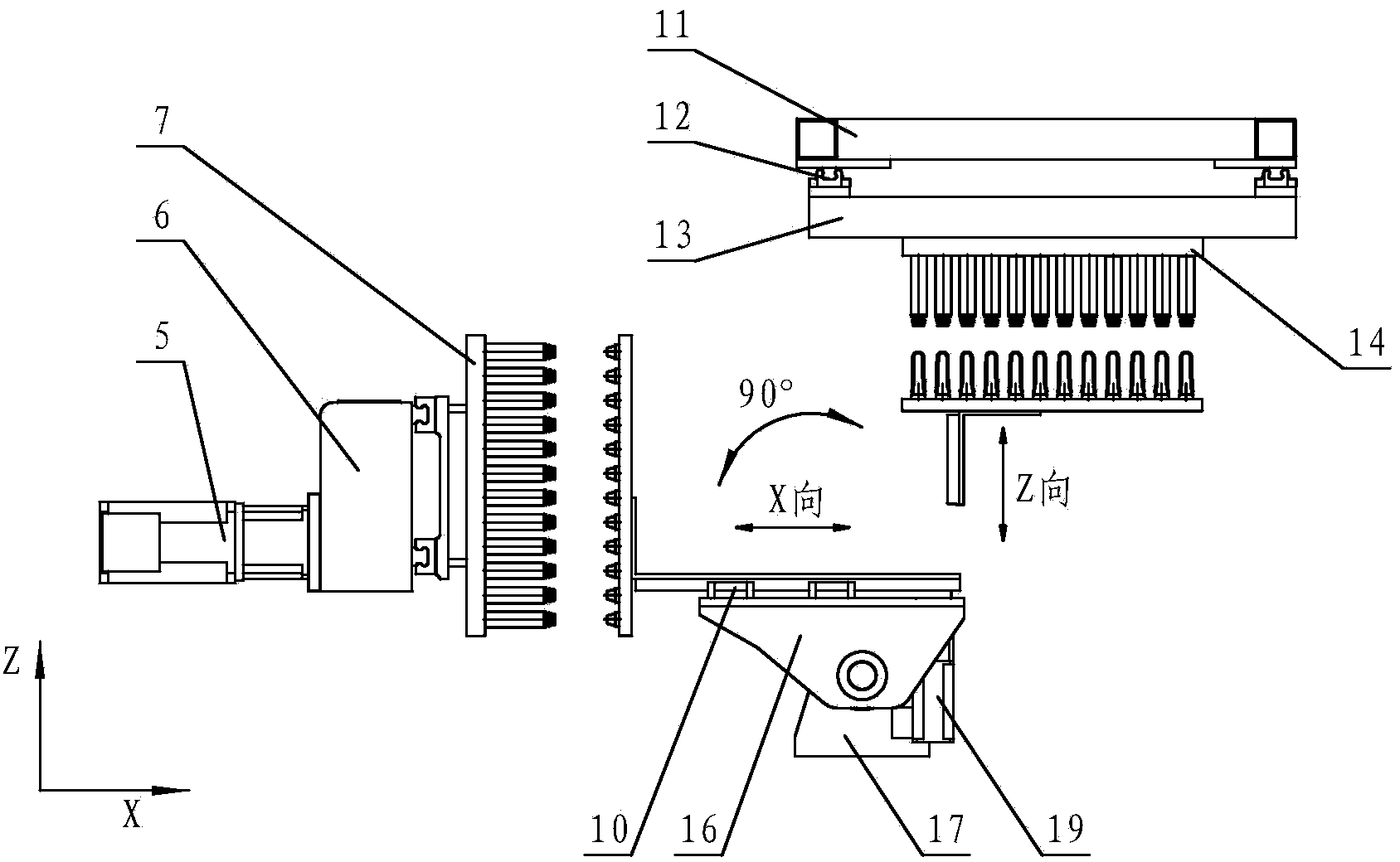
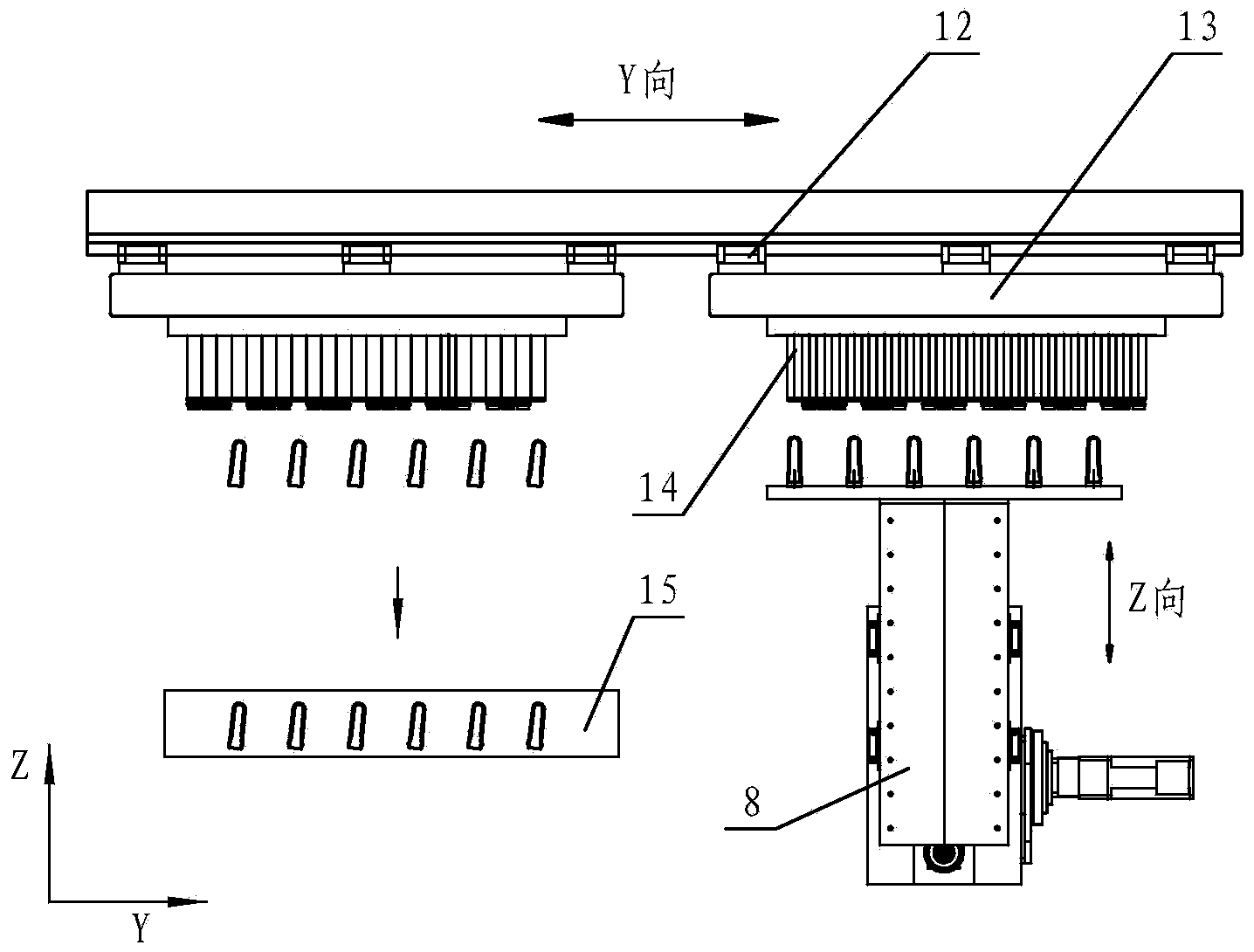
[0042] see Figure 1-Figure 3 , the preform take-out and cooling system, including the fixed mold 1 and the movable mold 2 arranged on the injection molding machine and the preform 3 between the fixed mold 1 and the movable mold 2, also includes a preform cooling device, the preform cooling The device includes a fixed seat 4, a first ball linear guide 6, a slider seat 18, a take-out jig 7 containing a cooling device, and a servo motor belt transmission mechanism 5, wherein the fixed seat 4 is connected with the head plate of the injection molding machine, and the fixed seat One end of 4 faces between the fixed mold 1 and the movable mold 2, and the servo motor belt transmission mechanism 5 is arranged on the fixed seat 4. The first ball linear guide 6 is arranged on the fixed seat 4, the first slider is arranged slidingly on the first ball linear guide...


PUM


Abstract

The invention relates to a bottle embryo taking out and cooling system. The system comprises a fixing die and a moving die that are arranged on an injection molding machine and a bottle embryo arranged between the fixing die and the moving die, and further comprises a taking embryo cooling device, wherein the taking embryo cooling device comprises a fixing seat, a first ball linear guideway, a sliding block seat, and a taking out jig that contains a cooling device and a servo motor belt transmission mechanism; the fixing seat is connected with the head plate of the injection molding machine; one end of the fixing seat faces the part between the fixing die and the moving die; the servo motor belt transmission mechanism is arranged on the fixing seat; the first ball linear guideway is arranged on the fixing seat; a first sliding block is arranged on the first ball linear guideway in a sliding manner; the sliding block seat is arranged on the first sliding block, and driven by the servo motor belt transmission mechanism to perform a linear to-and-fro movement on the fixing seat; the taking out jig that contains a cooling bottle embryo and a vacuum extraction bottle embryo is mounted at the front end of the sliding block seat. According to the invention, the system has the characteristics of flexibility for operation, high operating speed, low driving power, small controlling difficulty and stability for operation.

Description

technical field [0001] The invention relates to a preform take-out and cooling system. Background technique [0002] The preform injection molding machine is mainly composed of an injection molding machine and a multi-cavity mold. It is mainly used to produce plastic preforms. The injected preforms are further blow-molded to obtain products such as plastic bottles or medical packs. [0003] The production of the preform injection molding machine is carried out in a repeated cycle according to the process requirements of the product. Shortening the time occupied by each process and adopting the production method of parallel processes as much as possible are effective ways to shorten the cycle time and improve the production efficiency of the preform injection molding machine. [0004] Generally, the traditional preform injection molding machine is not equipped with a three-station preform fetching robot. The preform product can only be released from the mold after cooling an...

Claims


Application Information

Patent Timeline
IPC IPC(8): B29C45/42B29C45/72
CPCB29C45/42B29C45/7207
Inventor 梁继洪张元海方忠宝种明钟远城陈胜全
Owner GUANGDONG YIZUMI HIGH SPEED PACKAGING SYST COMPANY
Why Eureka
Eureka Blog
Learn More