Safety door automatic opening/closing device in injection molding machine and the like and method of controlling the same

an injection molding machine and safety door technology, which is applied in the direction of manufacturing tools, wing accessories,foundry moulding apparatuses, etc., can solve the problems of long waiting time, difficult to stop the safety door, and difficult to stop the cylinder rod, so as to reduce the cost and burden of wiring work

Inactive Publication Date: 2012-12-25
UBE MASCH CORP LTD
View PDF3 Cites 3 Cited by
  • Summary
  • Abstract
  • Description
  • Claims
  • Application Information

AI Technical Summary

Benefits of technology

[0031](1) It is possible to arbitrarily set and accurately control the opening / closing speed pattern of the safety door, and therefore, it is possible to make an attempt to shorten the time required to open / close the safety door and to shorten the molding cycle time.
[0032](2) It is possible to arbitrarily set and accurately control an open position of the safety door that allows a molded product to be taken out in the molding process, and therefore, it is possible to make an attempt to shorten the time required to open / close the safety door and to shorten the molding cycle time.
[0033](3) It is possible to set and accurately control an open position of the safety door that allows a mold to be carried in and carried out in the set-up process, and therefore, it is possible to make an attempt to shorten the time required to open / close the safety door and to shorten the set-up time.
[0034](4) It is no longer necessary to install a touch switch etc. configured to detect a contact of the safety door with an operator or obstacle during the closing operation of the safety door, and therefore, it is possible to reduce the cost and the burden of wiring work.

Problems solved by technology

Due to the characteristics of the air cylinder, it is difficult to stop the cylinder rod at a position set on the way of the stroke with high precision in an expanding / contracting operation of the cylinder rod.
Because of this, it is difficult to stop the safety door at a position other than the fully opened position and the fully closed position of the safety door, where the cylinder rod is located on both the stroke ends.
In particular, the larger a molding machine is, the longer the excessive opening / closing stroke of the safety door is, and therefore, the wasteful time (waiting time) becomes longer.
However, the operation by the air cylinder can be set to only two levels at the most, i.e., high speed and low speed, and it is difficult to freely set the speed, and control the speed and acceleration / deceleration (at the most, only the air throttle valve can be adjusted), and therefore, it is difficult to quickly open / close the safety door and shorten the cycle time thereby.
However, if a touch switch is attached to the safety door, it is difficult to wire it to the controller and at the same time, the cost is increased.

Method used


Image

  • Safety door automatic opening/closing device in injection molding machine and the like and method of controlling the same
  • Safety door automatic opening/closing device in injection molding machine and the like and method of controlling the same
  • Safety door automatic opening/closing device in injection molding machine and the like and method of controlling the same

Examples


embodiments

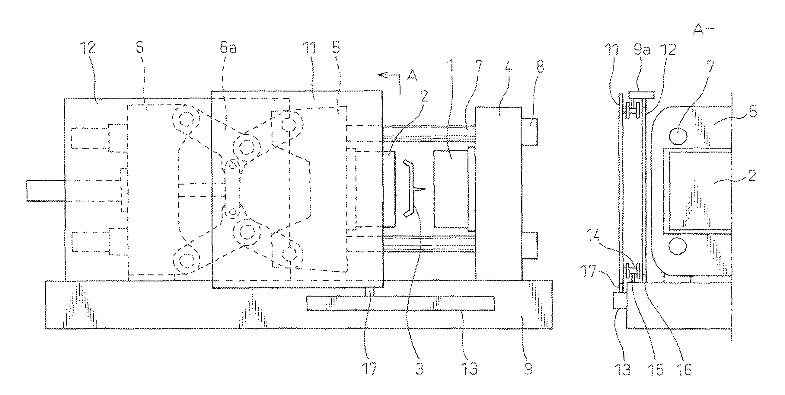
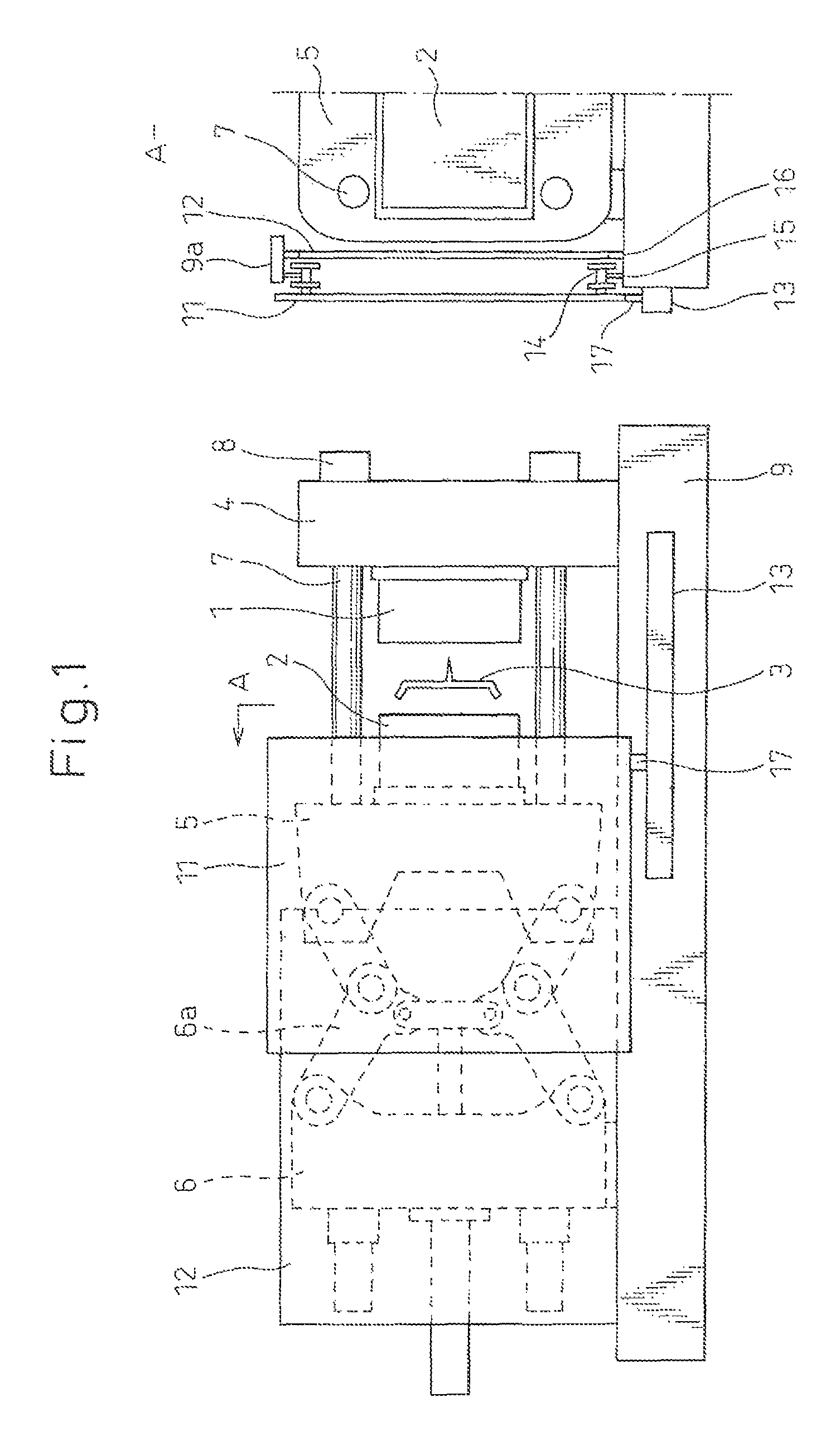
[0044]FIG. 1 shows the entire a mold clamping device comprising a safety door automatic opening / closing device according to the present invention. The embodiments of the present invention have the same basic structure as that of the prior art shown in FIG. 6 and FIG. 7, except that a touch switch is not attached to a safety door 11 and except for the configuration of an automatic opening / closing device 13.

[0045]The open position of a movable platen 5 and the open position of the safety door 11 in FIG. 1 are not a fully open position but a minimum necessary open position that allows a molded product 3 to be taken out, showing an open position without wasteful time required for the opening / closing stroke and operation, which enables the reduction in the cycle time.

[0046]A view A—in the direction of an arrow A on the right side shows a diagram when the safety door 11 etc. is viewed from the side. On the top surface of a machine base 9 and on the undersurface of a top part beam 9a (supp...


PUM

PropertyMeasurementUnit
thicknessaaaaaaaaaa
closing speedaaaaaaaaaa
torqueaaaaaaaaaa

Abstract

A safety door automatic opening / closing device is capable of freely (arbitrarily) setting and controlling the opening / closing speed and the open position to shorten a waiting time required to open / close a safety door and capable of eliminating a touch switch; and a method of controlling the same.

Description

CROSS-REFERENCE TO RELATED APPLICATIONS[0001]The present invention takes priority from Japanese Patent Application No. 2008-006899 filed on Jan. 16, 2008, the entire contents of which are incorporated herein as reference and continued in the subject application.TECHNICAL FIELD[0002]The present invention relates to a safety door automatic opening / closing device in an injection molding machine for molding a plastic product, a die cast machine for molding an aluminum product, etc., and a method of controlling the same.BACKGROUND ART[0003]An injection molding machine and a die cast machine mainly include a mold clamping device and an injection device. A mold including a fixed mold and a movable mold is closed by a mold clamping device and a cavity, which is a hollow space having the shape of a product, is formed therein, and plastic or aluminum in a molten state is injected into and filled in the cavity by the injection device and after the molten material has cooled and solidified, the...

Claims


Application Information

Patent Timeline
Patent Type & Authority Patents(United States)
IPC IPC(8): B22D17/32B29C45/84
CPCB22D17/26B22D17/263B29C45/84
Inventor ONO, HIDENOBUOGAWA, KOJI
Owner UBE MASCH CORP LTD
Why Eureka
Try Eureka