Molded article having hollow rim portion and process for producing articles

a technology of molded articles and rims, which is applied in the field of injection molding process, can solve the problems of large volumetric shrinkage, large molding cycle time, and high production cost of molded articles, and achieves significant material consumption and molding cycle tim

Inactive Publication Date: 2005-05-03
IAMS +1
View PDF19 Cites 3 Cited by
  • Summary
  • Abstract
  • Description
  • Claims
  • Application Information

AI Technical Summary

Benefits of technology

[0008]It is an object of the present invention to provide a gas assisted injection molding process which minimizes visible volumetric shrinkage in a final molded product.
[0009]It is another object of the present invention to provide a gas assisted molding process which reduces a clamp tonnage in an injection molding machine during an injection molding process.
[0010]It is a further object of the present invention to provide a gas assisted injection molding process which reduces the material consumed for the formation of the molded product and which reduces the total molding cycle time.
[0012]The presently disclosed process for producing an injection molded article with a hollow rim portion in an injection molding machine includes injecting a short shot of injection molding material into a mold via an injection nozzle, permitting a mold cavity to fill in an unbalanced manner as a result of a gas channel formed in a wall of the mold, closing the injection nozzle, and injecting a pressurized gas into the short shot of injection molding material, wherein the pressurized gas travels through the gas channel into a rim portion of the mold thereby expanding the injection molding material throughout the mold and simultaneously creating a hollow cavity within the rim portion of the mold.

Problems solved by technology

However, the manufacture of these articles has been far beyond the normal limits of a conventional injection molding processes.
The application of conventional gas assisted injection molding techniques to the manufacture of such articles results in visible volumetric shrinkage, require significant material consumption and molding cycle time, and produce a great deal of strain on the injection molding machine.

Method used


Image

  • Molded article having hollow rim portion and process for producing articles
  • Molded article having hollow rim portion and process for producing articles
  • Molded article having hollow rim portion and process for producing articles

Examples


Embodiment Construction

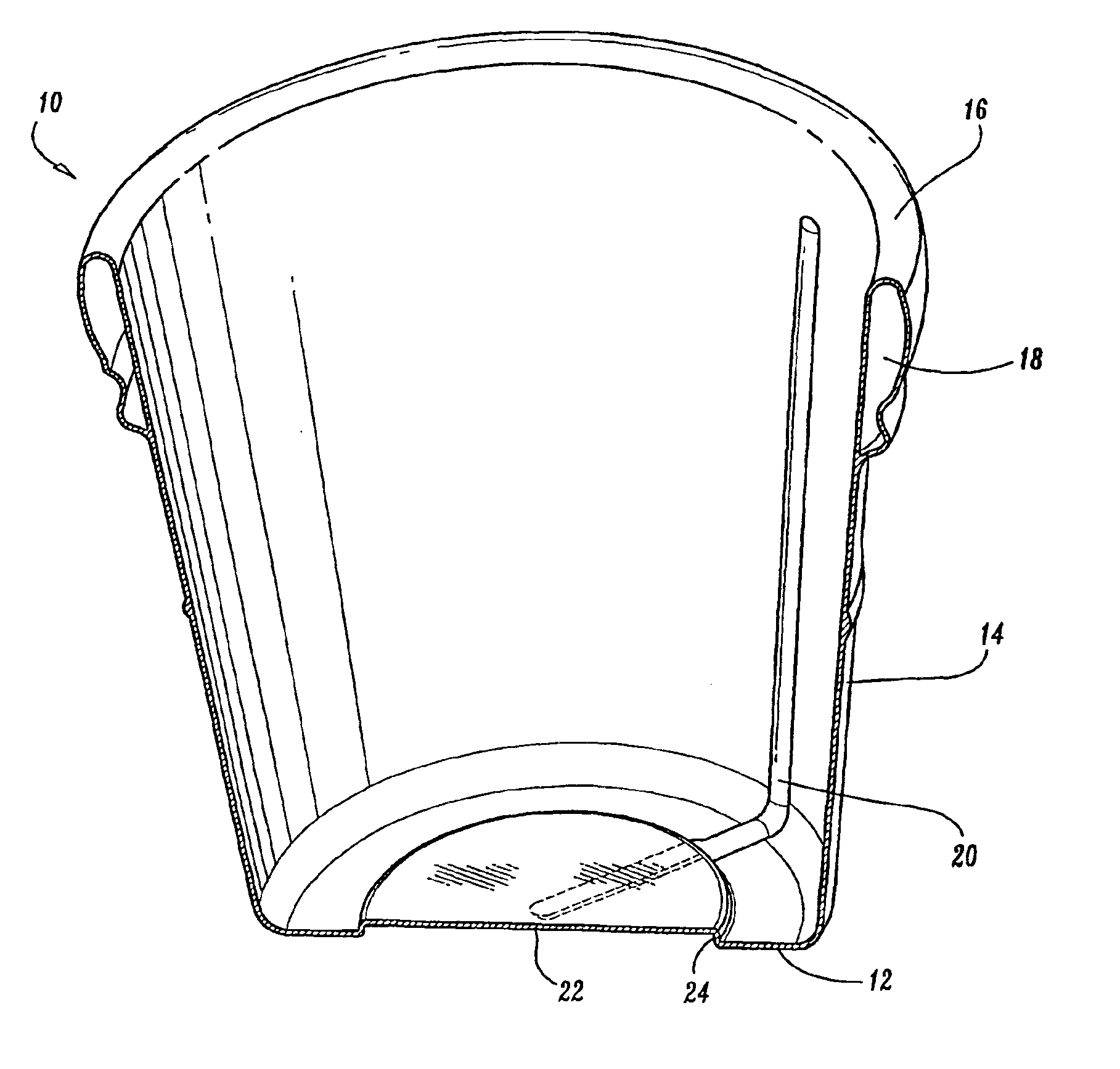
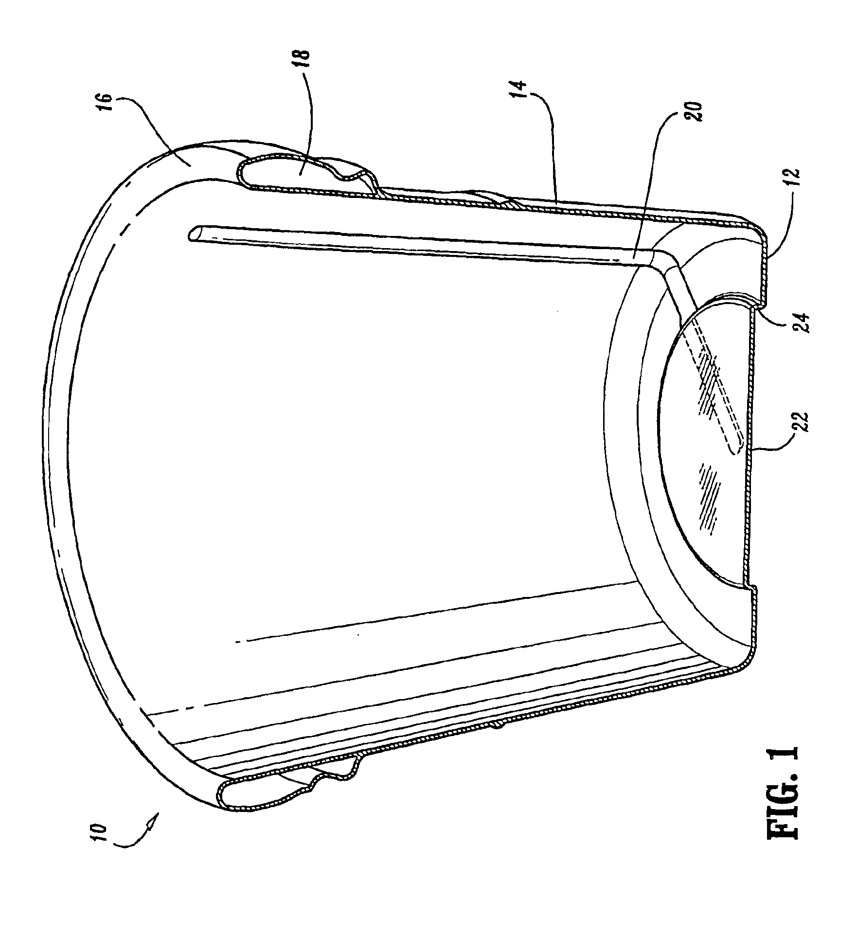
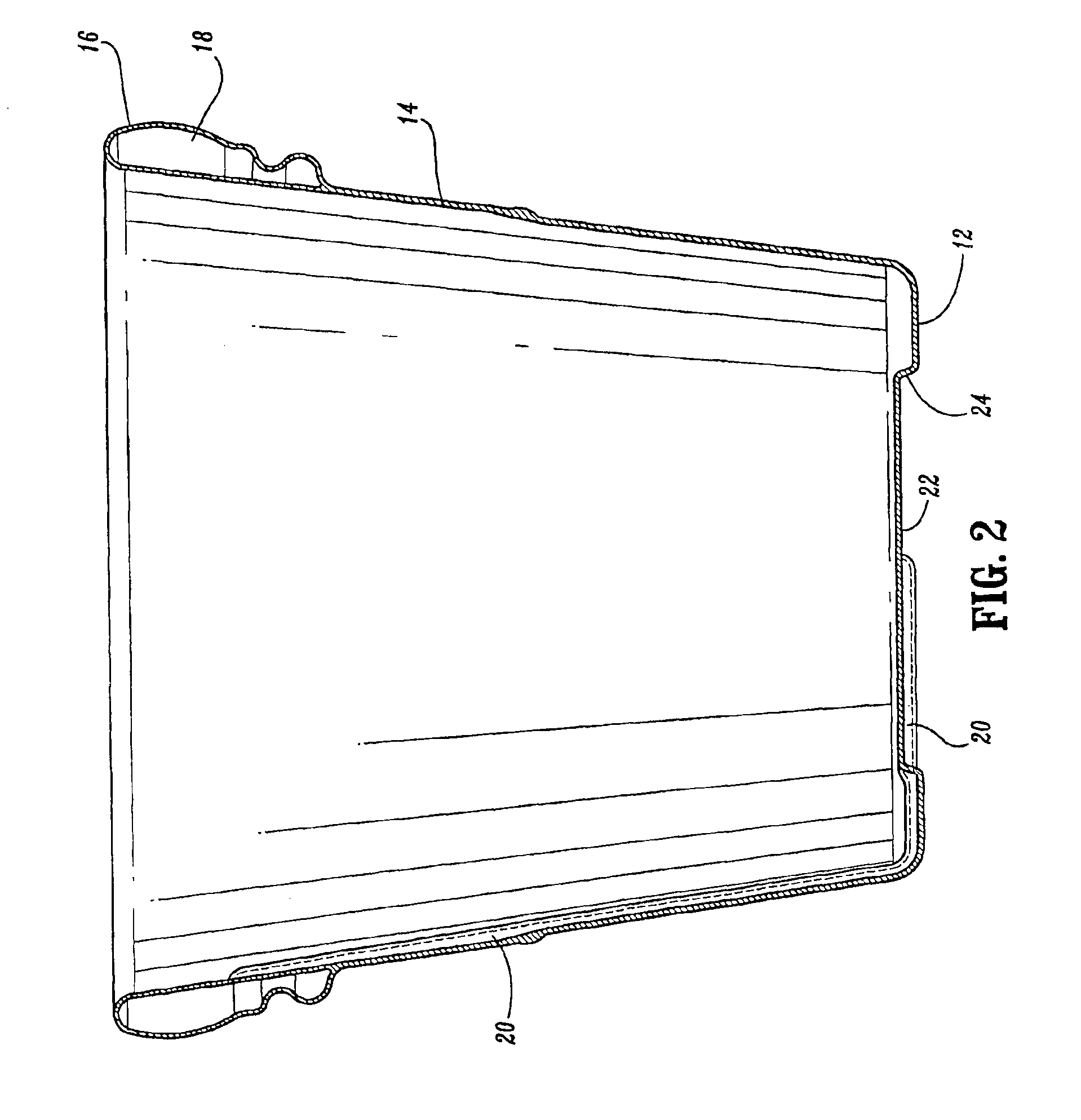
[0025]Articles formed according to the presently disclosed process are designed with a hollow closed geometry portion formed at a predetermined desired position along the periphery or surface of the particular article. For purposes of illustrating the process, the present disclosure illustrates and describes the process in connection with the formation of a flower pot having a hollow circular rim (i.e., the hollow closed geometry) formed at a top portion thereof. However, it will be understood that the presently disclosed processes may be utilized to form numerous different articles having a closed loop geometry portion formed integrally therewith.

[0026]Referring now in specific detail to the drawings, in which like reference numerals identify similar or identical elements throughout the several views, and initially to FIGS. 1 and 2, an illustrative example of the presently disclosed article is shown as a flower pot 10. The flower pot 10 includes a base wall 12 having an annular sid...


PUM

PropertyMeasurementUnit
temperatureaaaaaaaaaa
distanceaaaaaaaaaa

Abstract

A process for producing an injection molded article with a hollow rim portion in an injection molding machine including the steps of injecting a short shot of injection molding material into a mold via an injection nozzle, permitting a mold cavity to fill in an unbalanced manner as a result of a gas channel formed in a wall of the mold, closing the injection nozzle; and injecting a pressurized gas into the short shot of injection molding material, wherein the pressurized gas travels through the gas channel into a rim portion of the mold thereby expanding the injection molding material throughout the mold and simultaneously creating a hollow cavity within the rim portion of the mold.

Description

CROSS REFERENCE TO RELATED APPLICATION[0001]The present application claims priority of U.S. provisional application Ser. No. 60 / 225,522 filed on Aug. 15, 2000, the entire contents of which are hereby incorporated by reference.BACKGROUND[0002]1. Technical Field[0003]The present disclosure relates to an injection molding process and, in particular, to a gas assisted injection molding process for forming molded articles having a hollow portion formed in a closed geometric portion thereof, for example, a rim of a pot, container or the like. In addition, the present disclosure relates to a molded article and, in particular to a molded article having a hollow portion formed therein as a result of the gas assisted injection molding process.[0004]2. Description of Related Art[0005]Gas injection molding techniques are generally known, such as the technique described in U.S. Pat. No. 5,401,459. Gas injection molding can generally be described as a process where gas is injected into a plastic ...

Claims


Application Information

Patent Timeline
Patent Type & Authority Patents(United States)
IPC IPC(8): B29C45/17
CPCB29C45/1704Y10T428/13B29L2031/7136B29C2045/1727
Inventor RICE, FRANK J.LAABS, JR., BRUCE A.KNICKLEBINE, DAVE P.
Owner IAMS
Why Eureka
Try Eureka