

Gas turbine
A technology of gas turbines and machines, applied in mechanical equipment, engine components, engine functions, etc., can solve problems such as insufficient separation of dirt
- Summary
- Abstract
- Description
- Claims
- Application Information
AI Technical Summary
Problems solved by technology
Method used
Image

Examples
Embodiment Construction
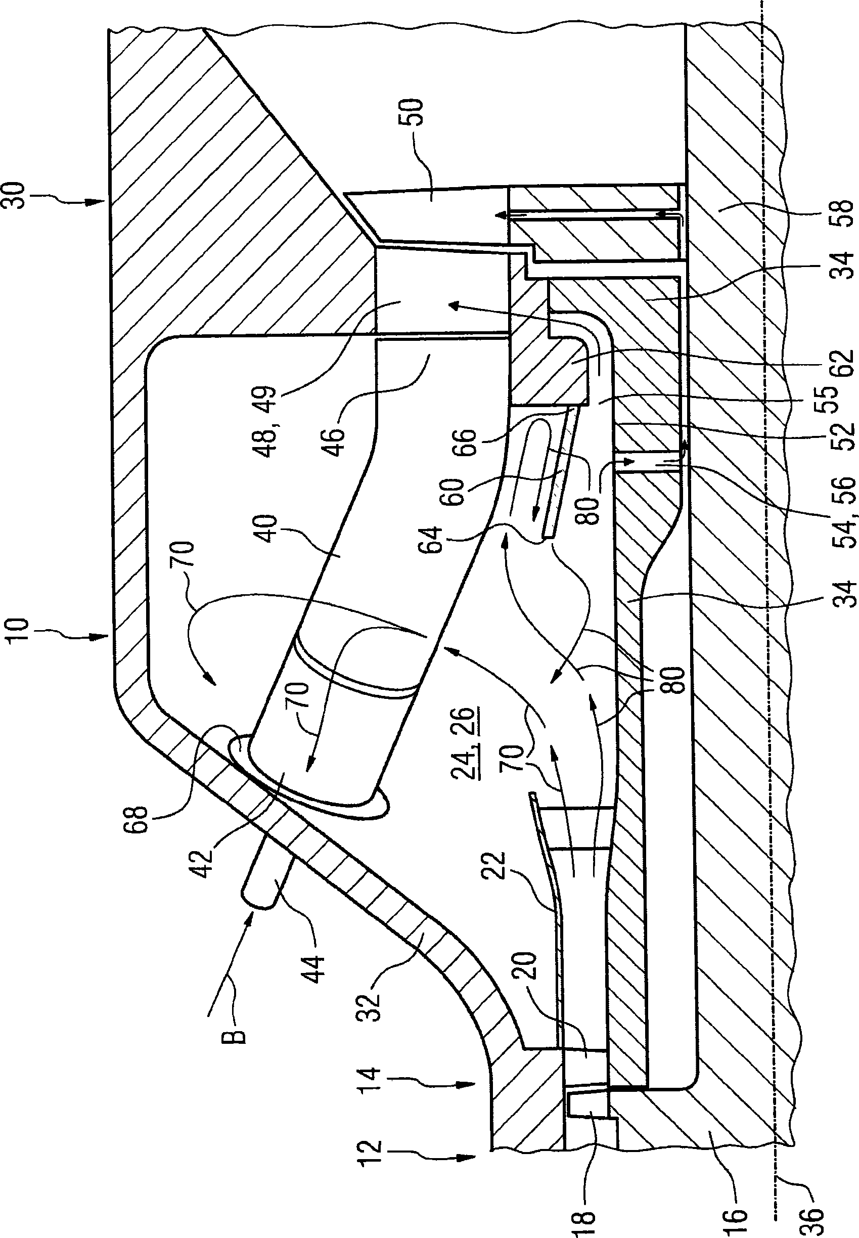
[0016] The drawing shows in detail a longitudinal section through the axial section of an axially flowable stationary gas turbine 10 between the outlet-side end of the compressor 12 and the turbine inlet. Of the compressor 12 of the gas turbine 10 , only the last compressor stage 14 is shown, with rotor blades 18 arranged on the rotor 16 and guide vanes arranged downstream in the air flow with respect to the air flowing through the compressor 14 20. Furthermore, a compressor diffuser 22 is provided downstream of the compressor guide vanes 20 , through which the pressurized air flowing from the end of the compressor 12 can flow into the hollow chamber 24 . The hollow chamber 24 , also called the combustor booster 26 or simply the booster, is located between the compressor 12 and the turbine 30 when viewed in the axial direction. Seen in the radial direction, the supercharger 26 is arranged between the outer housing 32 and the inner rotor 16 or shaft guard 34 . The shaft guard...
PUM
 Abstract
Description
Claims
Application Information